Motivation: Search and Rescue Robots often have to travel over rough terrain and could carry important supplies such as medical equipment. In this project, the rough terrain was simulated by an obstacle course and the robot was built to autonomously navigate through it and reach a light source.
This is a video showing a search and rescue robot autonomously navigating an obstacle course and then delivering a medical kit. I built this robot as part of a team, where I was responsible for the sensing and control for the autonomous navigation.
As seen in the video, the robot is capable of climbing a step using its front two spoke-like wheels and the treads on the back. It can then go through a curved chute avoiding the walls and then find a light source to then deposit a ‘medical kit’.
The image below shows the placement of the sensors in order to accomplish the tasks in the course and the electronics layout that allowed for sensor readings to be used for autonomous navigation.


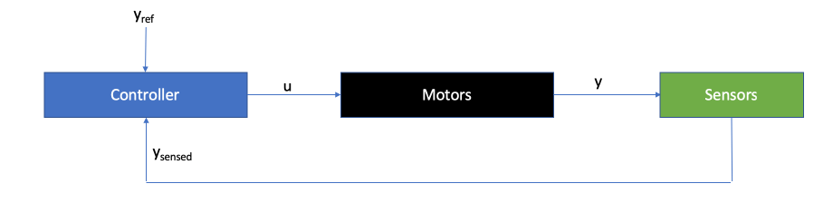
The general principle used to navigate autonomously was to use appropriately placed sensors to give us feedback on the state of the robot. This information would then be used to control the torques (motors) on the robot wheels in order to steer it through the course.
Wall Traversal:
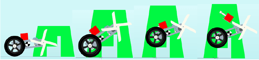
The accelerometer was used to infer the orientation of the robot which allowed the identification of which one of the four stages (as shown below) the robot was at. Based on which stage the robot was at, the right torques where then applied to the wheels to get it over the wall. Additionally, the accelerometer was used to determine whether the robot landed in a tilted orientation after the wall traversal, i.e., if it landed on one of the four spokes. If this was the case, the front spoked were rotated slowly until the accelerometer read the values corresponding the the flat orientation.
Chute Navigation
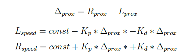
Proportional-Derivative (PD) control was used to navigate the chute using feedback from the proximity sensors that were placed at a 45 degree forward facing angle on the front of the robot. The difference between the readings of the two sensors (on either end of the robot) was taken to infer which side of the chute the robot was closer to. Then using experimentally determined gains, the torques on the two back wheels were adjusted to ensure that it could navigate through the chute. Using proportional gain only would lead to a jerky adjustment, but taking the derivative allows the smooth traversal. The formulas below show the general control strategy.
Finding the light and delivering the med-kit:
To find the light, the light sensor readings were used to facilitate feedback control. The light sensors, like the proximity sensors, were placed on the left and right side of the robot. This allowed us to sense which side of the robot the light source was and appropriately differentially steer the wheels in order to reach the destination.
Finally, an accelerometer was placed on the med-kit arm in order to rotate the arm to an appropriate angle where the med-kit would drop into the basket once the robot retracted. Additionally, FEA was used to analyze the torques on the med-kit arm to ensure that it could withstand the weight of the med-kit, as shown below.

