How are things made? Why are they made the way they are? These two questions intrigue me and to help answer them I visited several factories. This blog documents the manufacturing processes that I observed while providing simple explanations for why things are manufactured the way they are.
Blog
Apparel
BlogI visited an apparel factory that specializes in mass producing shirts for men. The process is divided into 8 general stages, which I’ve explained below:
Step 1: The Raw Material
The factory buys rolls of cloth that it then loads onto the machine shown below:

Step 2: Rough, Manual Cutting:
The roll of cloth is then roughly cut manually into smaller, more manageable pieces where individual parts of the shirt are then cut.

Step 3: Printing a template
Each of the parts of the shirt is outlined on a computer to scale. Multiple parts are then combined into one document that gets printed. They are combined on the computer in a way that maximizes the area covered by the parts, to ensure that as little cloth as possible gets wasted. The images below shows the preview on the computer and an industrial printer printing the template.


Step 4: Using the template on cloth to form the parts of the shirt:
Each of the templates is then attached on top of several sheets of cloth that were cut in Step 2 as shown below.

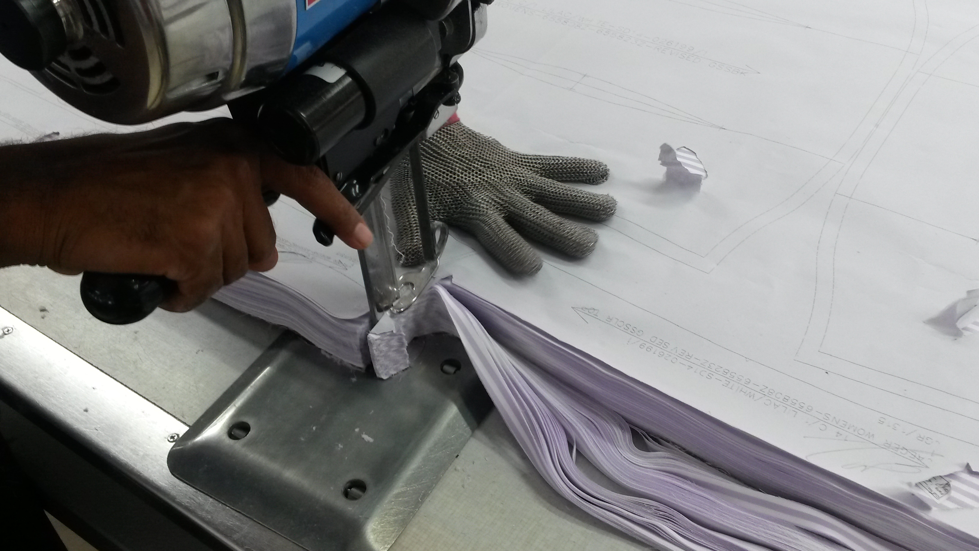
The pieces are then cut using electronic hand-cutters. These cutters come in two varieties:
a) A movable clamp and blade. Here, the cloth is not firmly clamped down by the machine and the worker must use his hand to firmly secure the cloth in place. However, the worker can move the cutter. This cutter is not precise as the worker can freely move the blade. It is therefore used to roughly and quickly cut around the lines of bigger pieces as the image below shows.
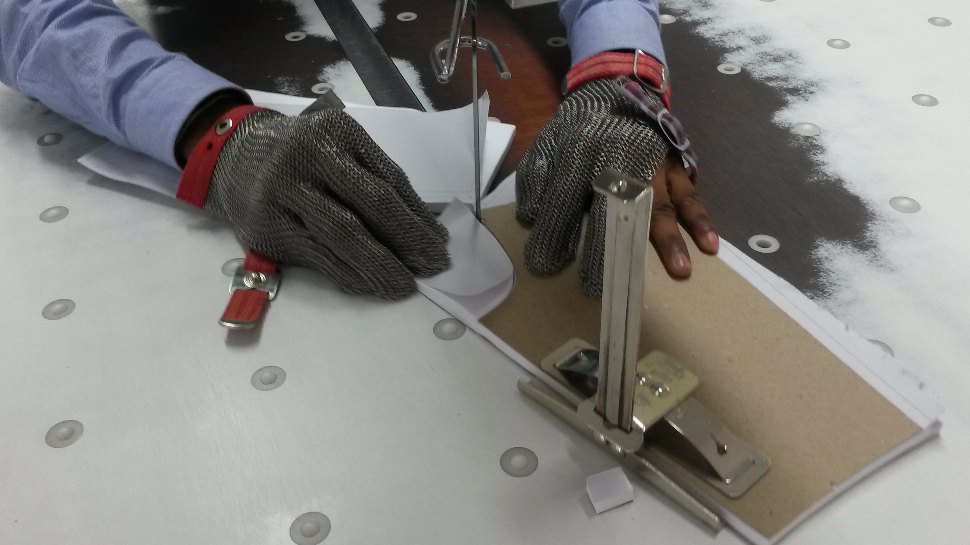
b) A fixed clamp and blade. Here, instead of moving the blade the worker moves the clamped cloth into a blade that runs continuously. This is used for more precise operations with the assistance of a cardboard piece cut out in the same shape as the part that needs to be cut as shown below.
With the help of both of these cutters (each for operations with different levels of precision), multiple copies of the parts of the shirt are cut.
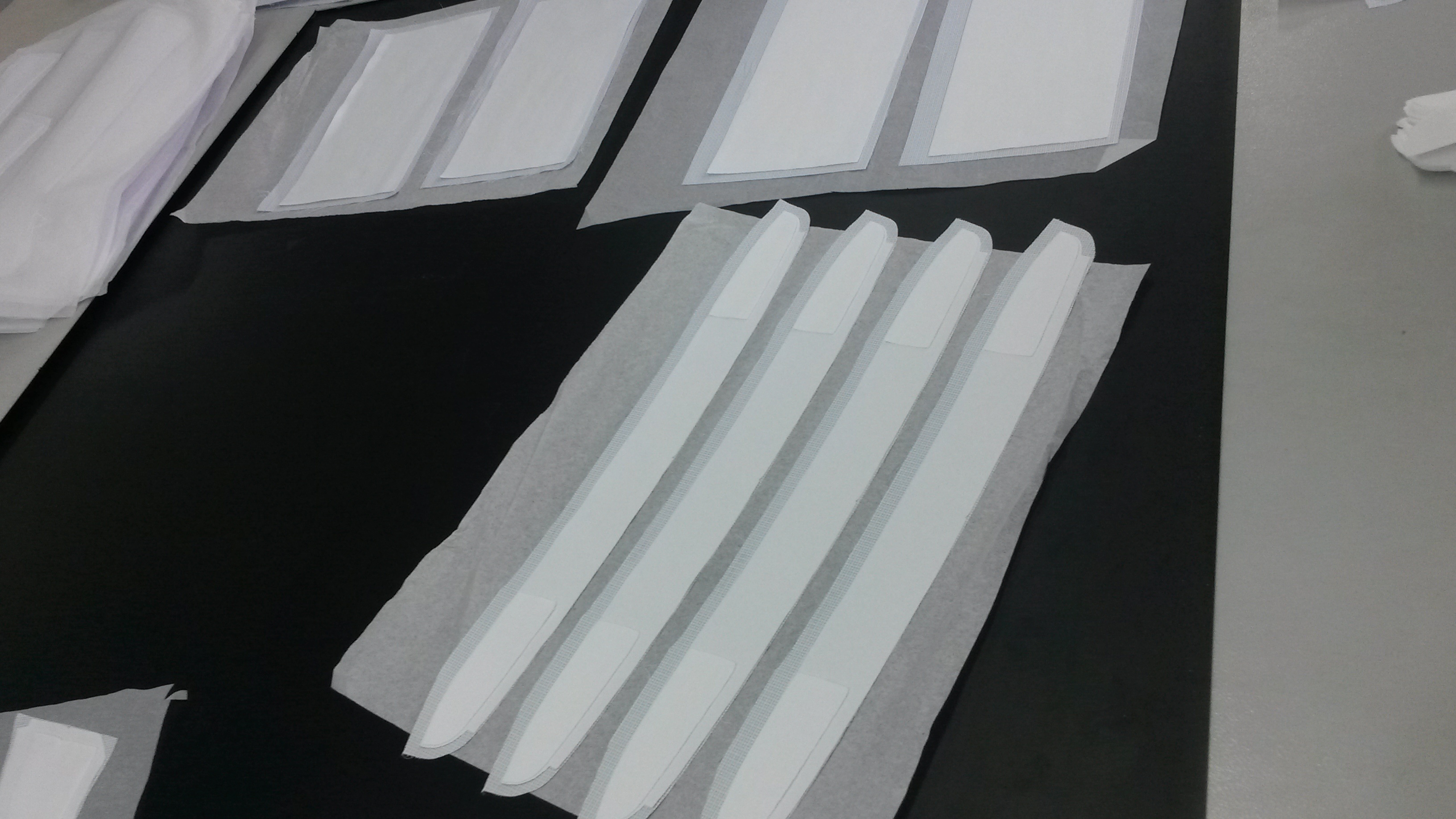
Step 4: Making some parts firmer:
You might have noticed the collar, end of the sleeve and front (where the buttons are) of formal shirts are stiffer than the rest of the shirt in order to prevent wrinkles and give the shirt a more defined shape. This is enabled by combining several pieces of the thin cloth into one thicker piece. Pieces of the cloth are layered on top of each other above a special, heat-resistant paper and sent through a heater.
The heater is set to a particular temperature so that the pieces of cloth melt very, very slightly to bind together. The cloth is not directly placed on the rubber as it would stick to the smooth surface of the rubber. The paper, however, has a rough texture, which means its surface is uneven- this prevents the cloth from sticking to it. Additionally, the paper has a much higher melting point and does not melt even slightly which further prevents it from sticking to the cloth.
The layers are bound together using a heater to create the firmness that some parts of the shirt require.
Step 5: Stitching the intricate parts
The intricate parts, such as the brand logo is stitched by an automated computer-numerically controlled (CNC) machine. Code is fed into the machine which instructs it to move a particular distance, stay there for a particular amount of time while using one of the input threads. A code is set of each of the brands the company makes shirts for.
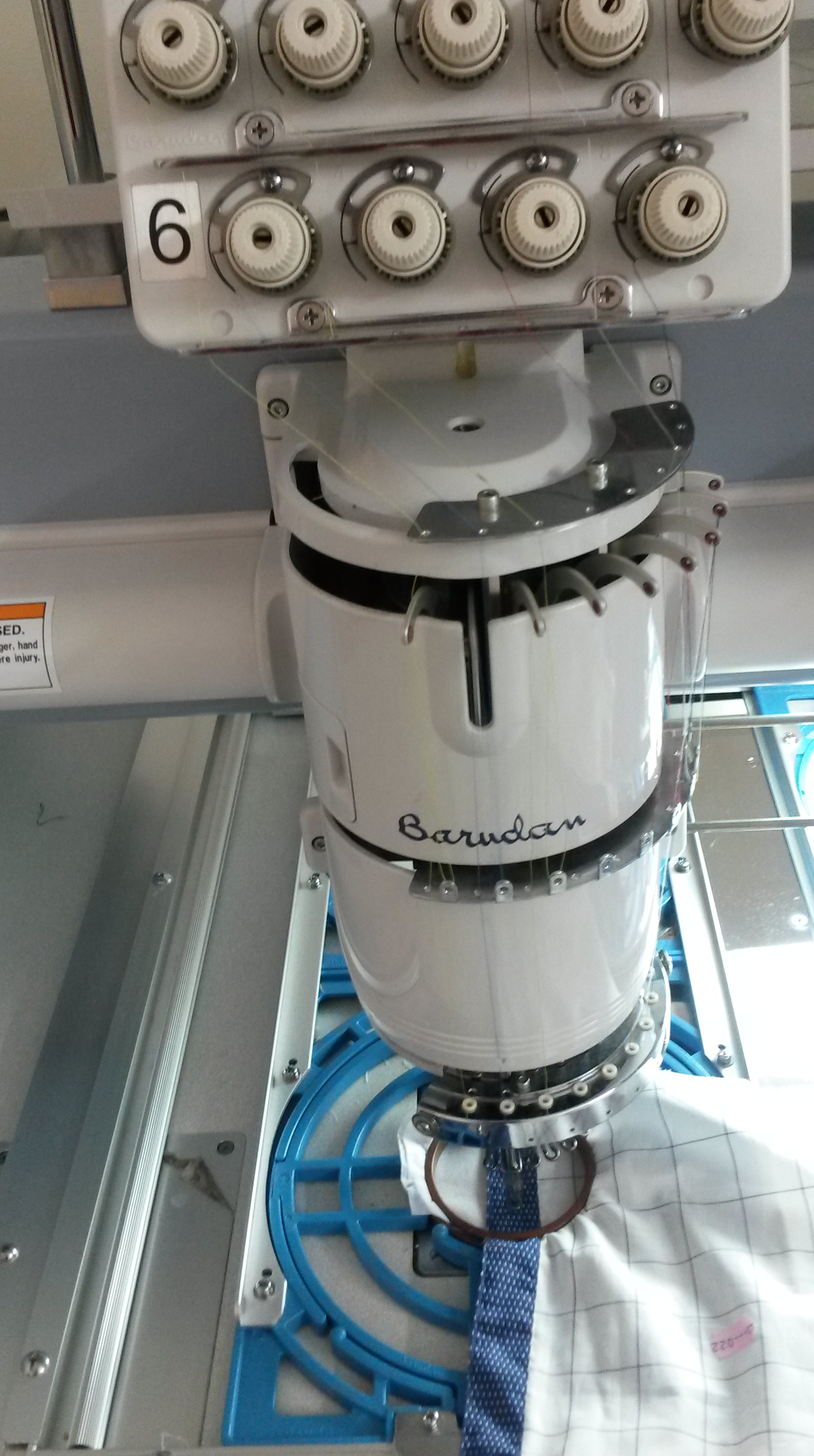
The bottom of the CNC is an automated sewing machine with takes the input on thread and continuously stitches it on the cloth.
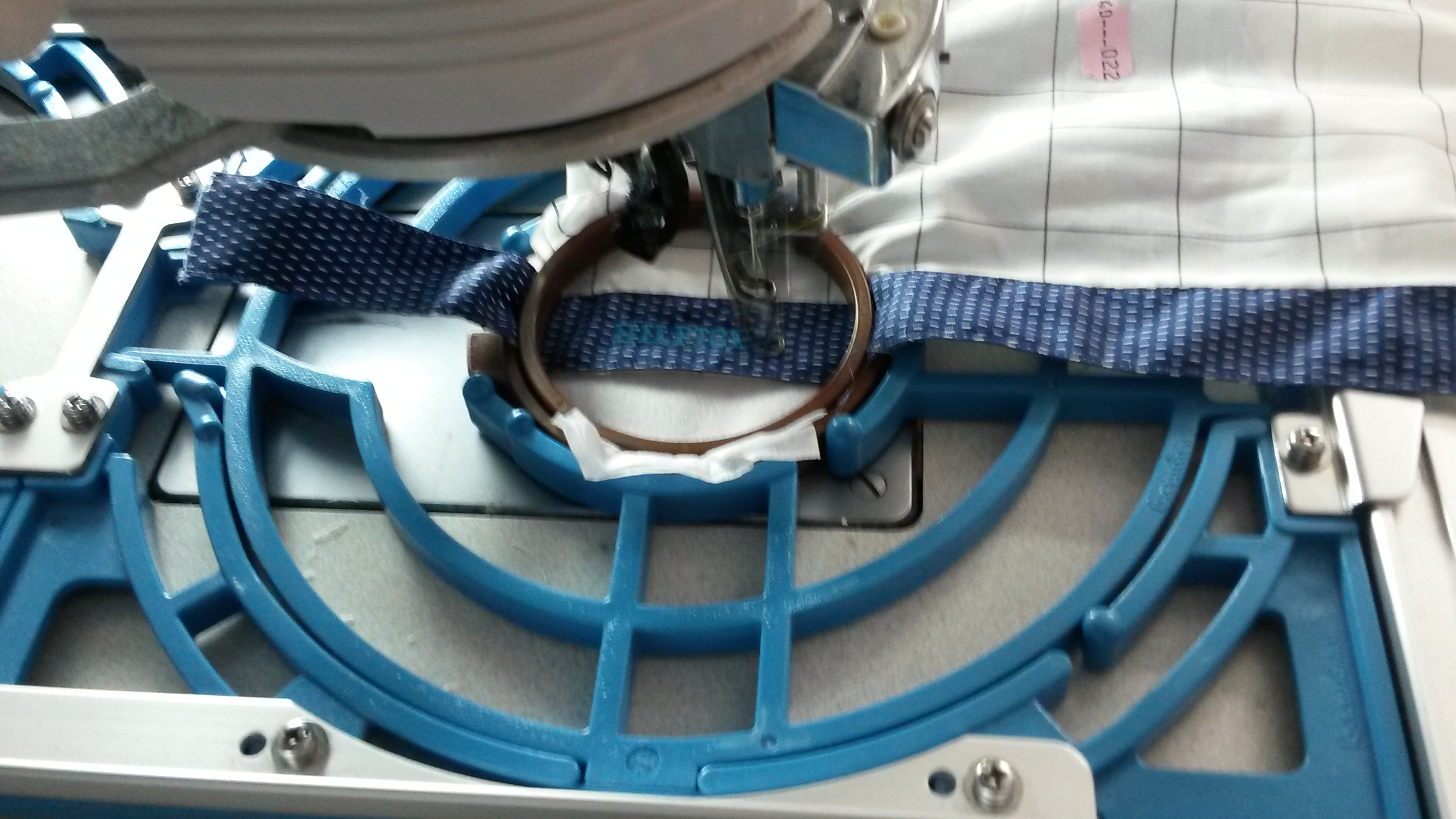
This is not done by hand, as it would not be as precise or as quick.
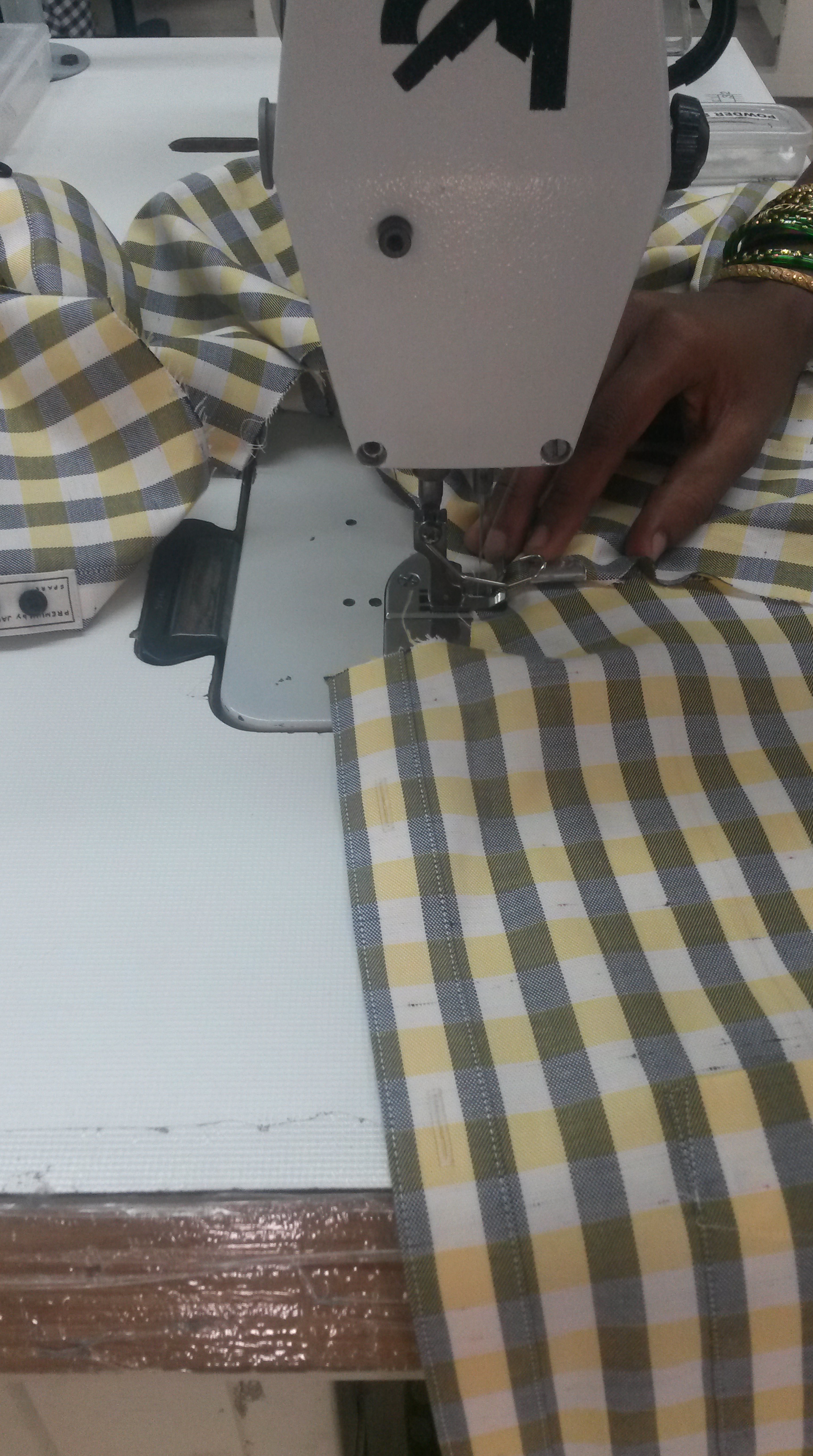
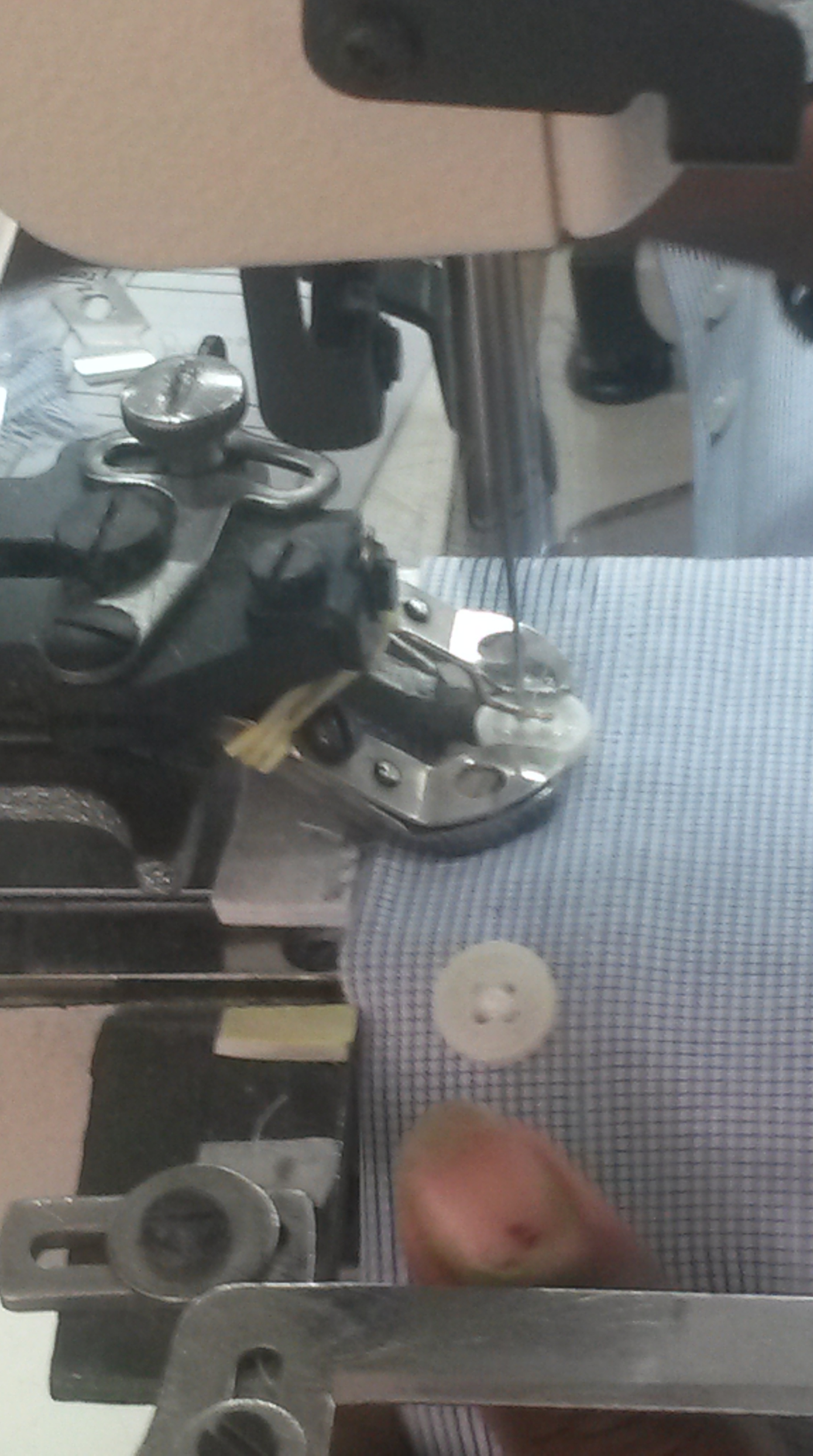
Step 6: Stitching the parts together:
Each of the parts (some made firmer, some with the brand name stitched), are brought into an assembly line, with an additional part being added on in each row.

Semi-automatic sewing machines are used throughout the process by operators to stitch the parts together and add components, such as buttons. The images below show this in action.
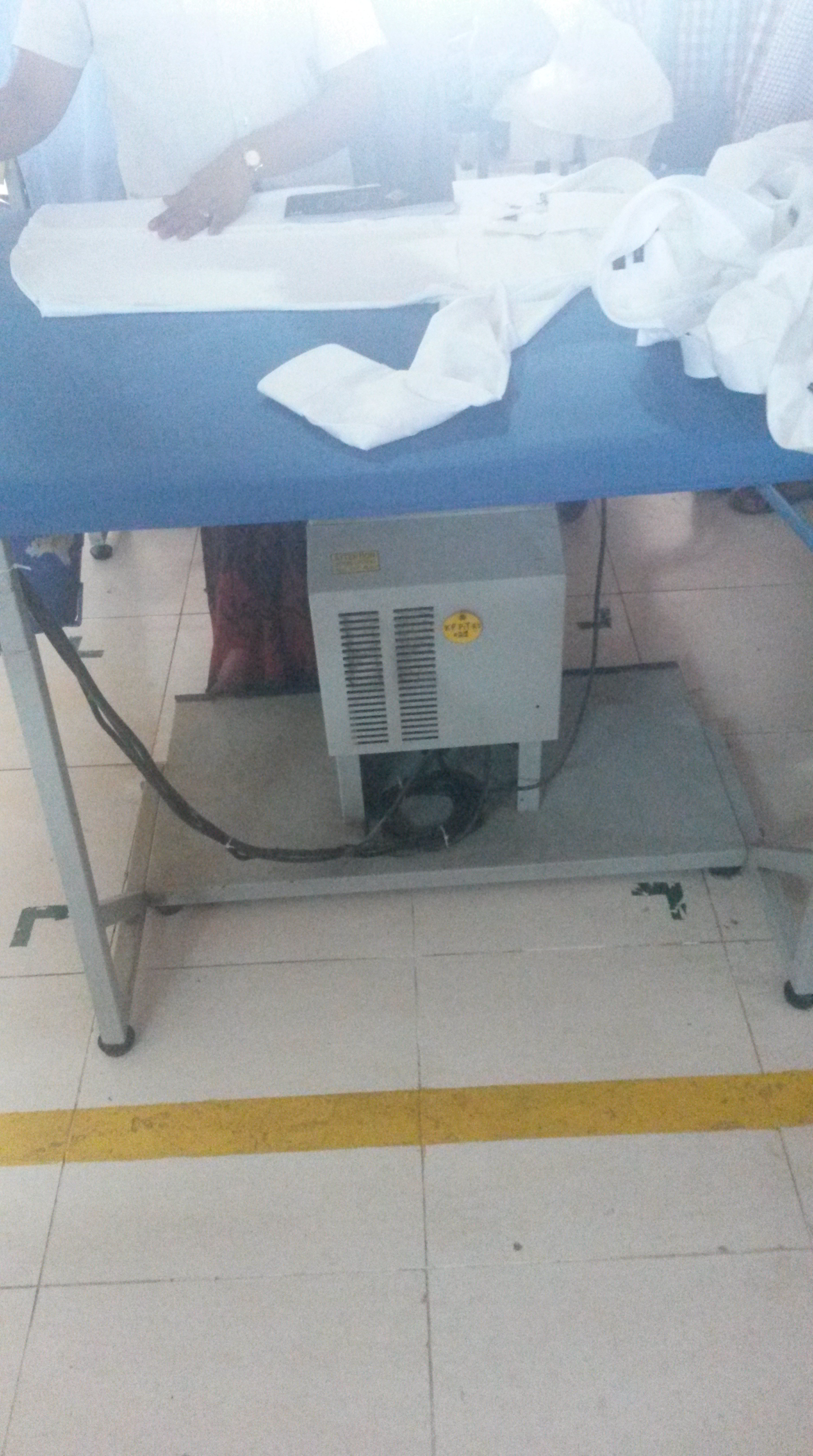
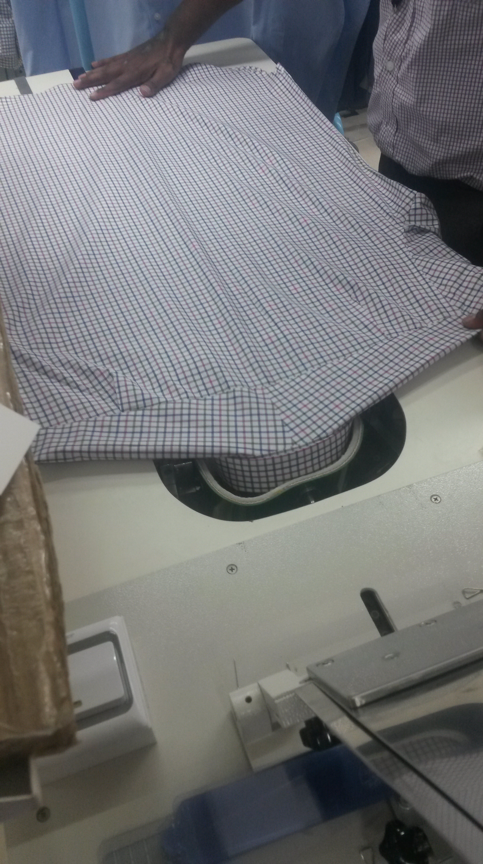
Step 7: Ironing
The assembled t-shirt is then manually ironed. The table used is a specialized one with a machine placed underneath that sucks in the air above it to create a pressure drop right above the table. This helps the shirt stick more firmly onto the table, making it easier to iron and remove all wrinkles.

Step 8: Packing
The shirts are folded and packed on specialized tables that have slots in them for the collar to make it easier to fold.

After the shirt is packed it is transported to shops where people like you and me buy them!
Furniture
BlogI visited a factory that manufactures a variety of furniture from cabinets to desks, using both wood and steel. This factory interestingly had a high level of automation and had widespread use of CNC’s (Computer Numerically Controlled Machines) which minimised the number of steps required to manufacture the final product. Here’s a look at the process:
Step 1: The Raw Material:
There are two main raw materials used in the process:
1) Engineered Wood.
Engineered wood refers to wood constructed using wood fibres or veneers and gluing them together with an adhesive, under high temperature and pressure. This is preferred to solid wood for multiple reasons including:
a) It can be made denser and therefore stronger.
b) It can be designed in such a way so that it’s properties are uniform throughout, as the deficiencies in wood (such as knots and cracks) are removed.
c) Engineered Wood is versatile and is manufactured in multiple grades, sizes and thickness.
d) It is also environmentally friendly, as it can be produced from relatively small trees and even waste scraps of wood. In addition, less wood needs to be used, as it is stronger than solid wood.
e) Engineered wood products are sometimes cheaper than solid wood products, as less wood needs to be used to provide the required strength.
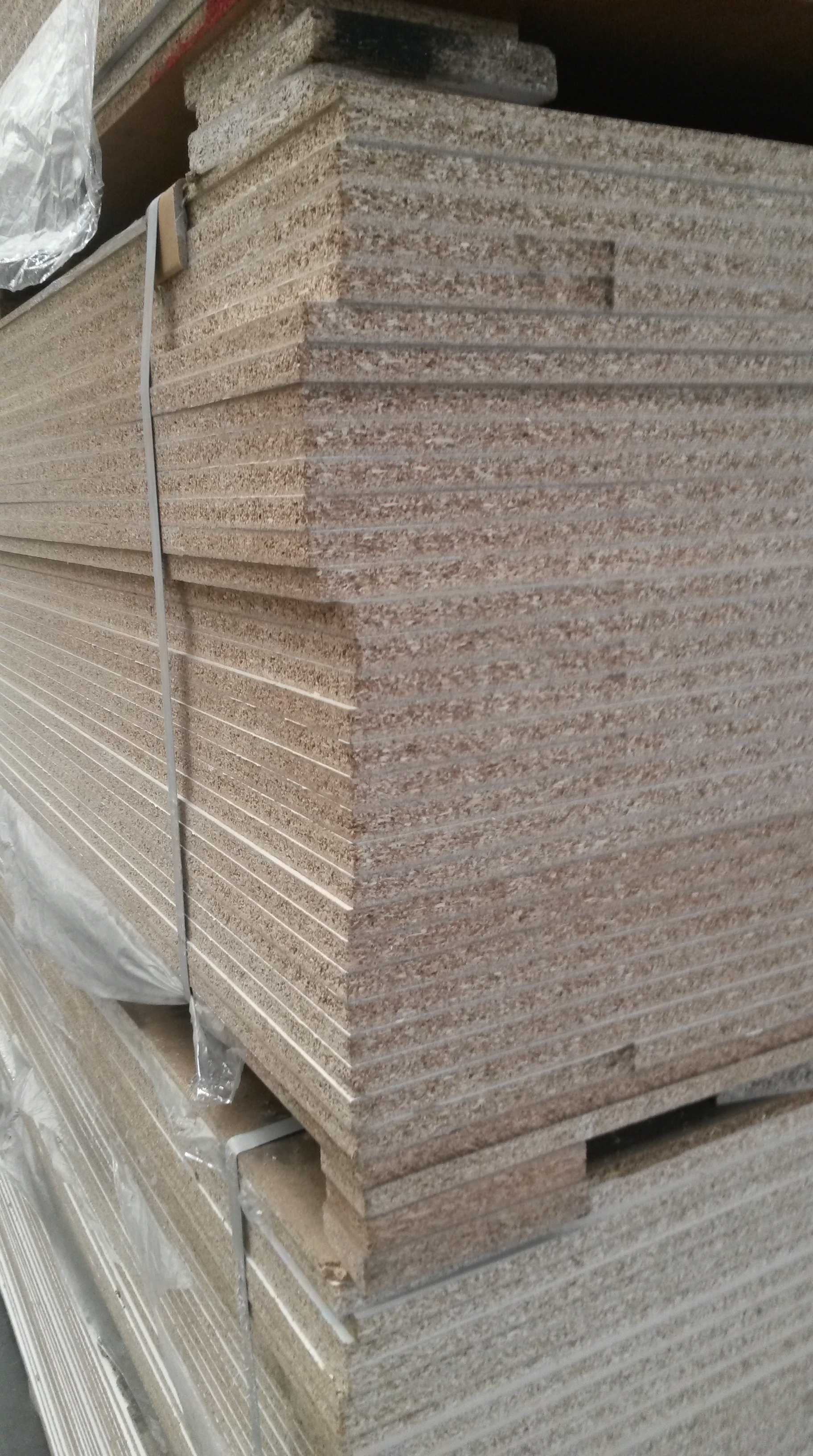
There were two types of engineered wood used in the factory I visited- Laminated Medium Density Fibreboard (density of about 750-800 kg/ m3) and Laminated Particle Board (density of about 650- 700 kg/ m3). The image below shows the engineered wood, with the fibres easily visible:
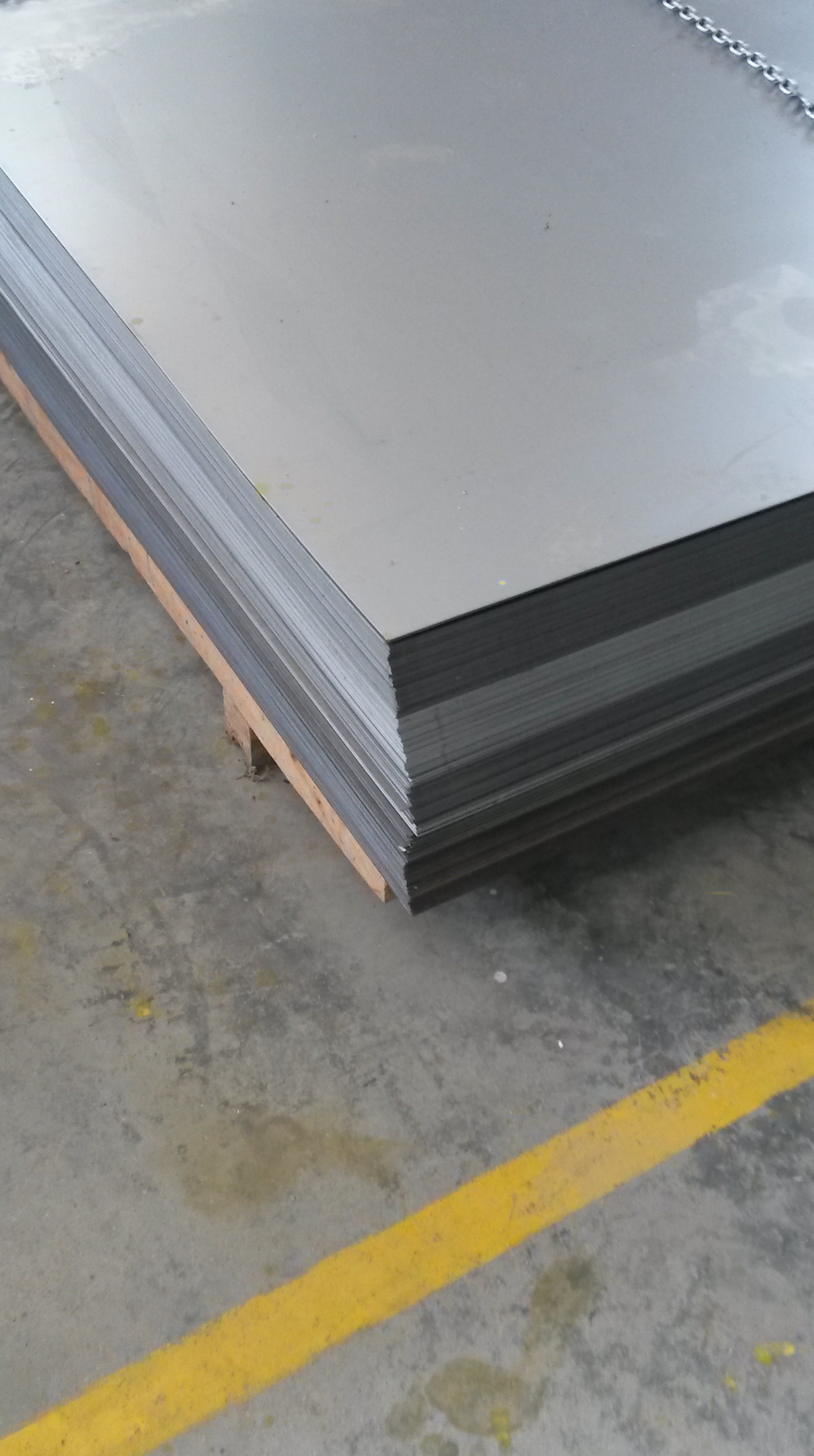
2) Steel
Steel is used in many of the products to form the frame in which the wood is held.
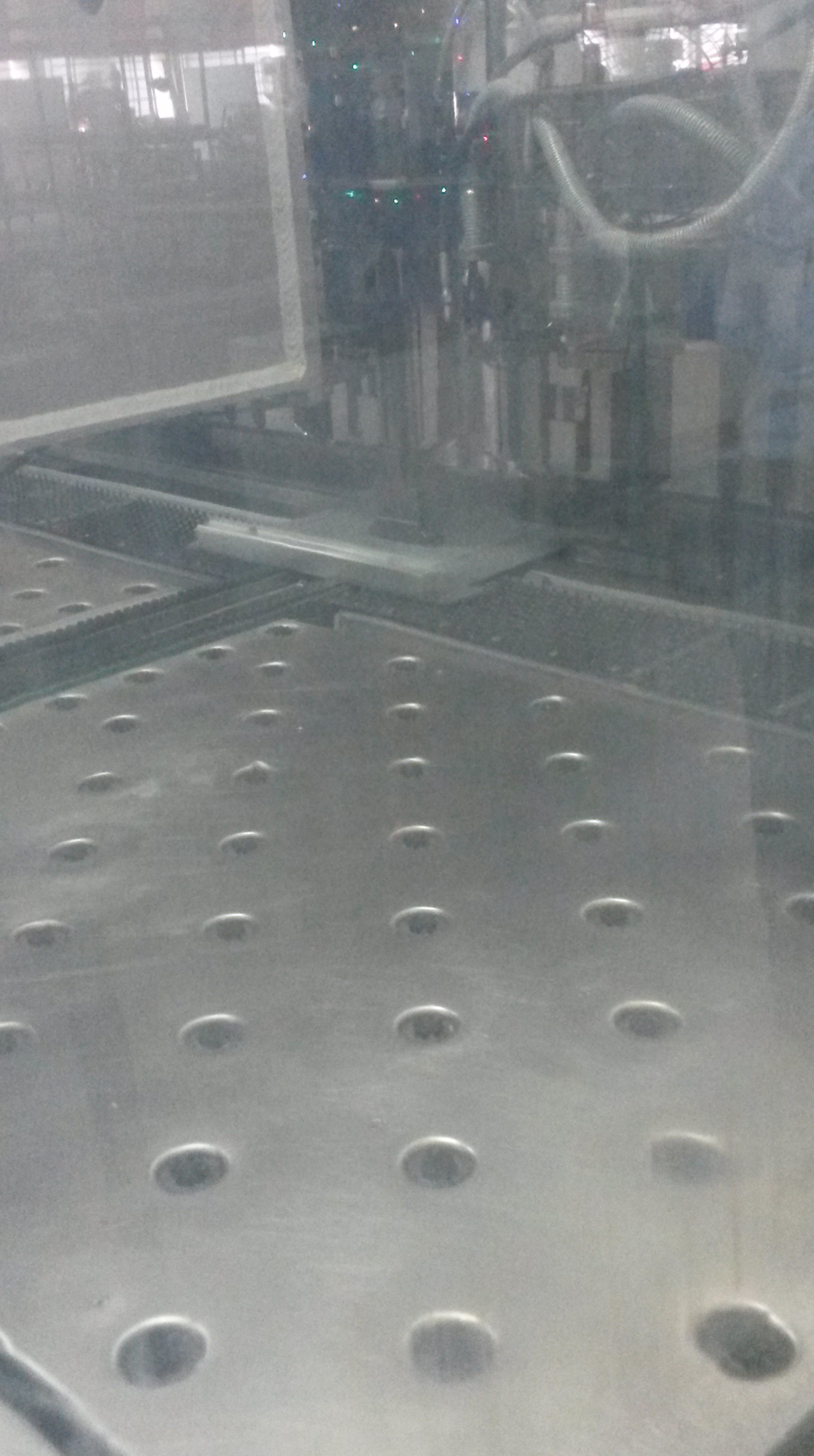
Step 2: Using CNC machines to cut and drill:
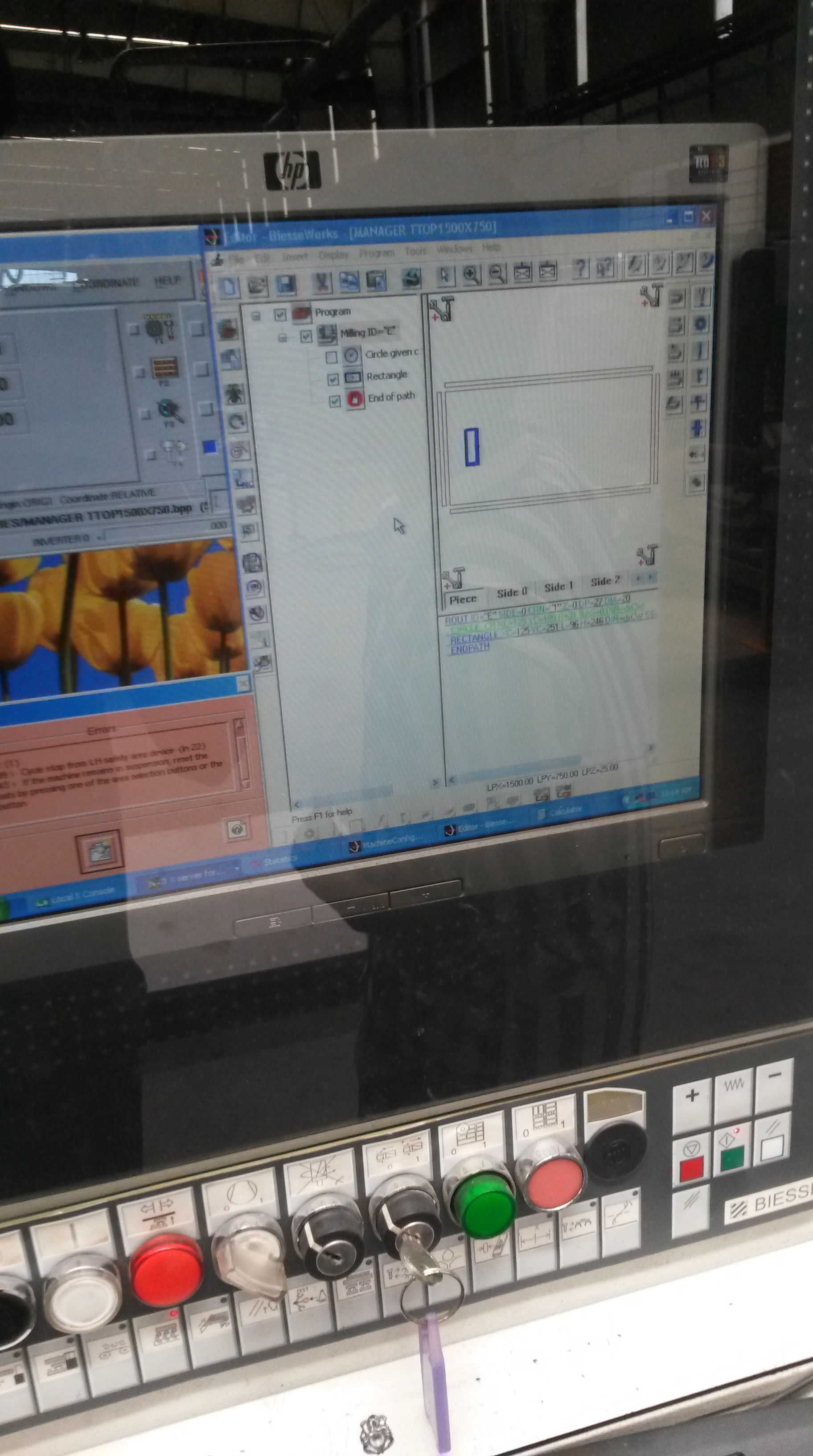
The machine comes with preloaded software on which you insert the drawing of the final shape of the wood/ steel you want. The software then instructs the various tools in the machine to perform the task. It does this with a program that instructs the specific tool required to proceed to certain x, y, z coordinates for a specific period of time. CNC’s offer tremendous flexibility for manufacturing- it allows you to cut any shape required and drill exactly where you want helping make a variety of products.
The image below shows the software being used:
Once it has been instructed the machine cuts where required:
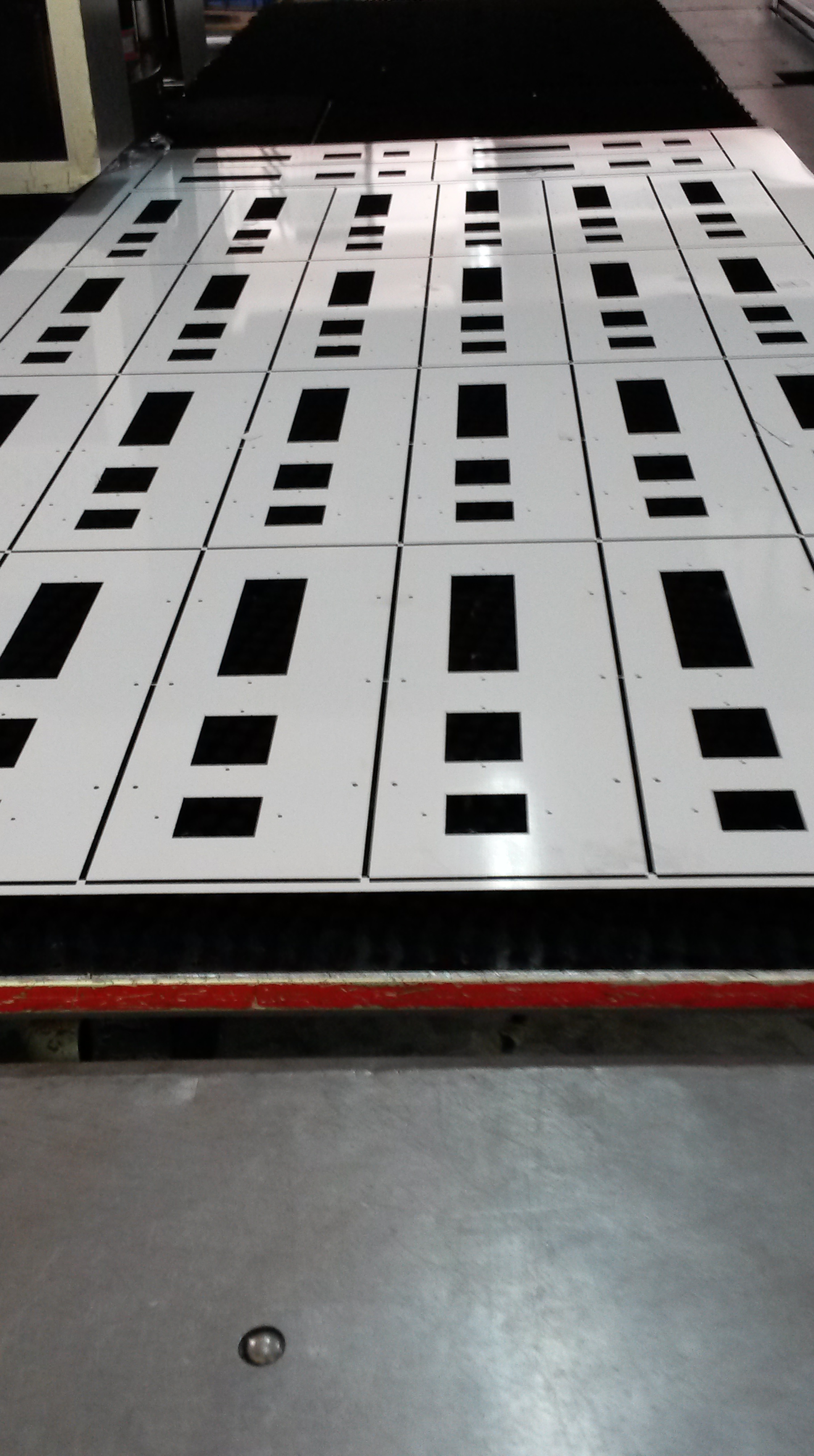
The machine is also capable of drilling, to produce identical pieces of wood shown below:
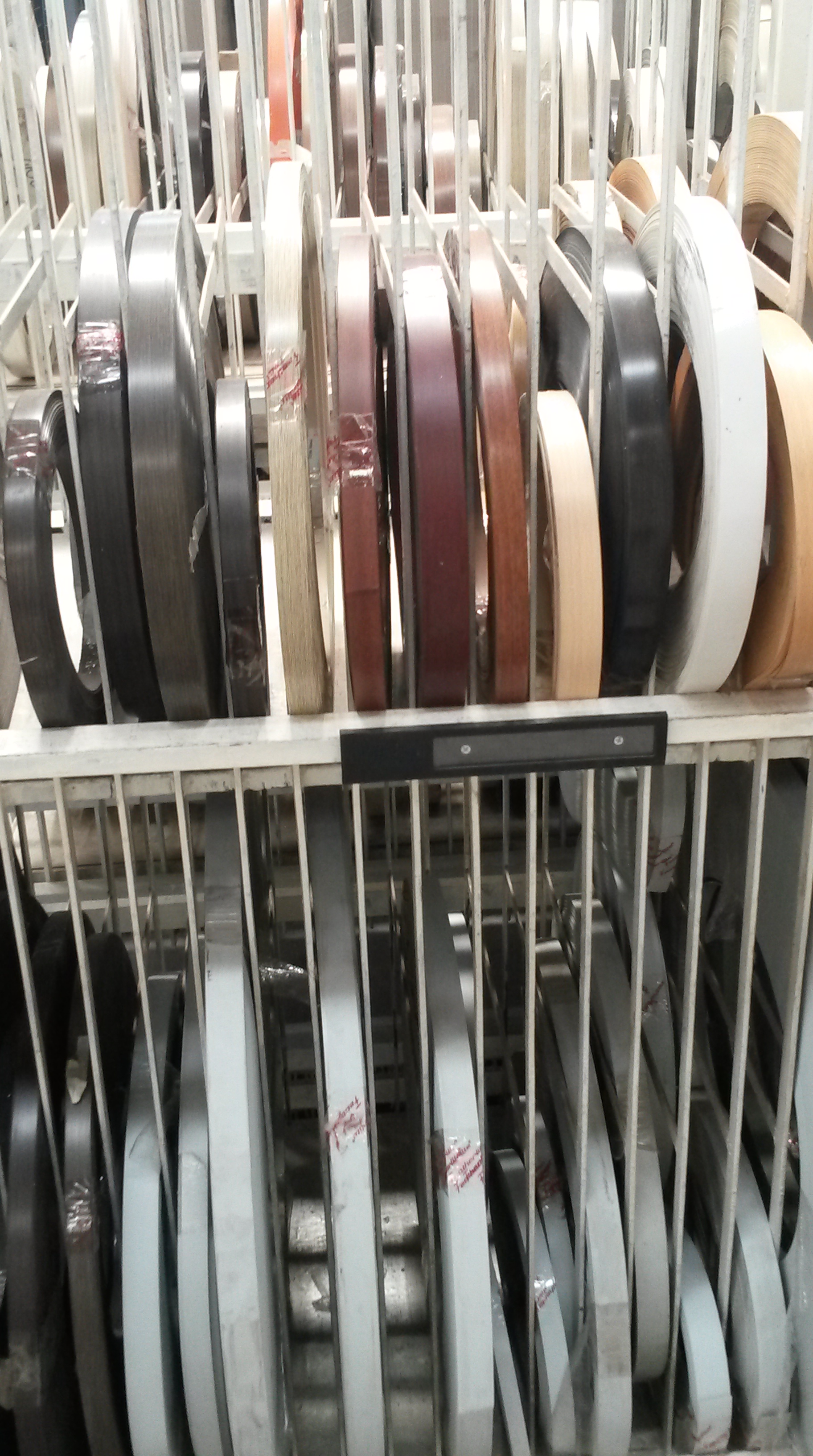
Step 3: Edge-Banding:
The wood has the top and bottom laminated but not the sides. Thus, the side of the wood that is going to be exposed to the customer needs to be coated. The edge- banding material comes in large varieties as the image below shows:
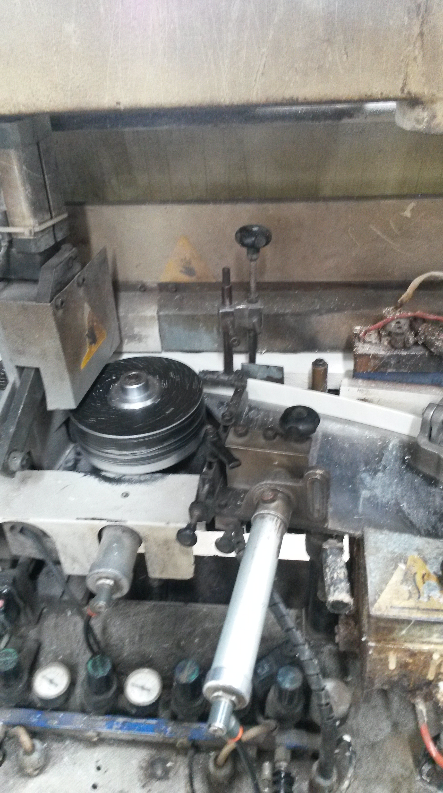
The bands are then inserted into a machine alongside the wood. It then glues the bands onto the wood by continuously coating the side of the wood with a glue, as shown below. There is also a sensor in the machine that cuts the band as soon as the slab of wood has passed.
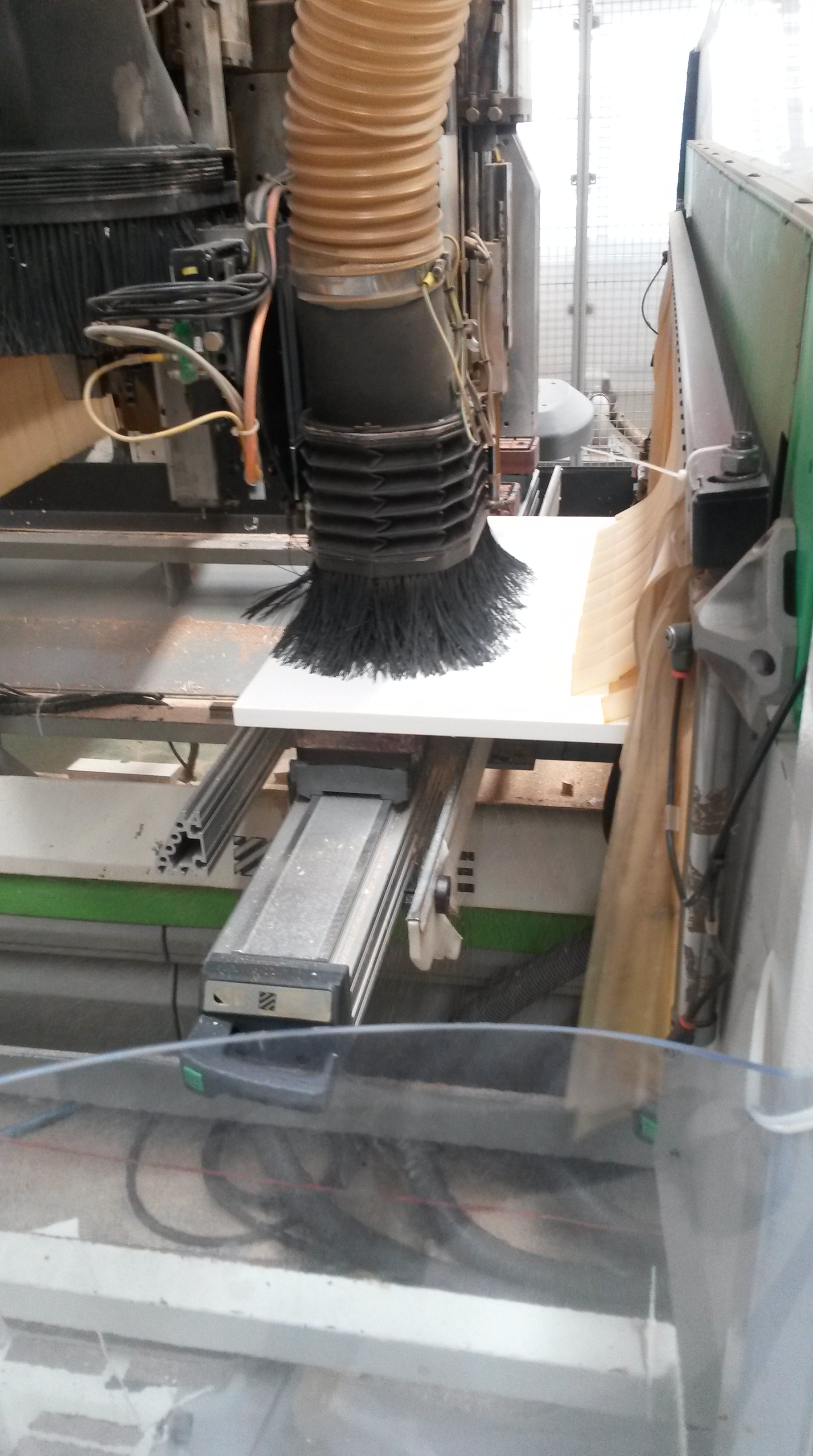
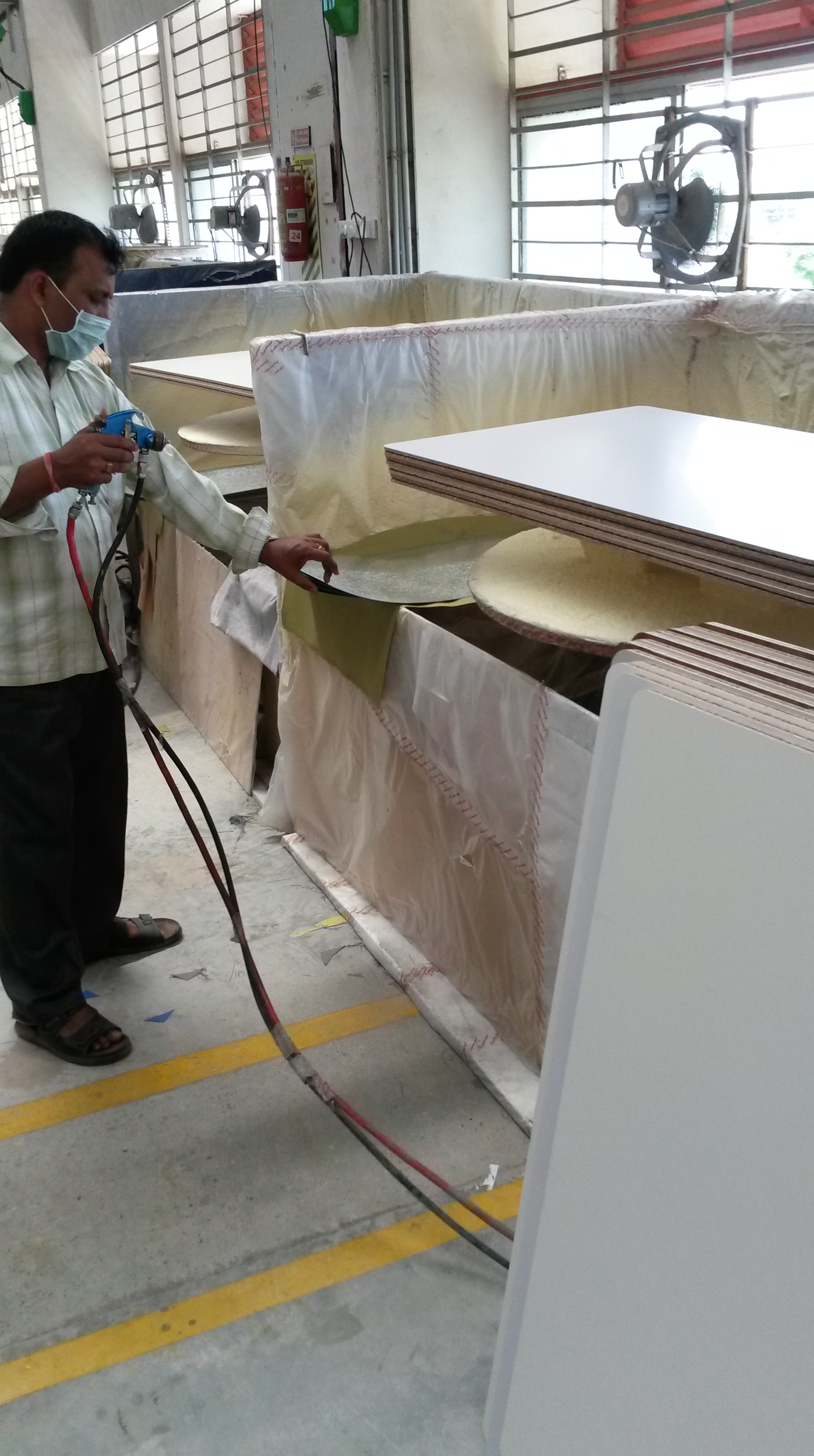
Step 4: Coating:
Often, the wood used for the panel in front of desks needs to be coated in cloth or needs to be made magnetic to that papers can be attached to it. This is done by spraying an adhesive on the wood and then applying either the cloth/ magnetic material, as shown below:

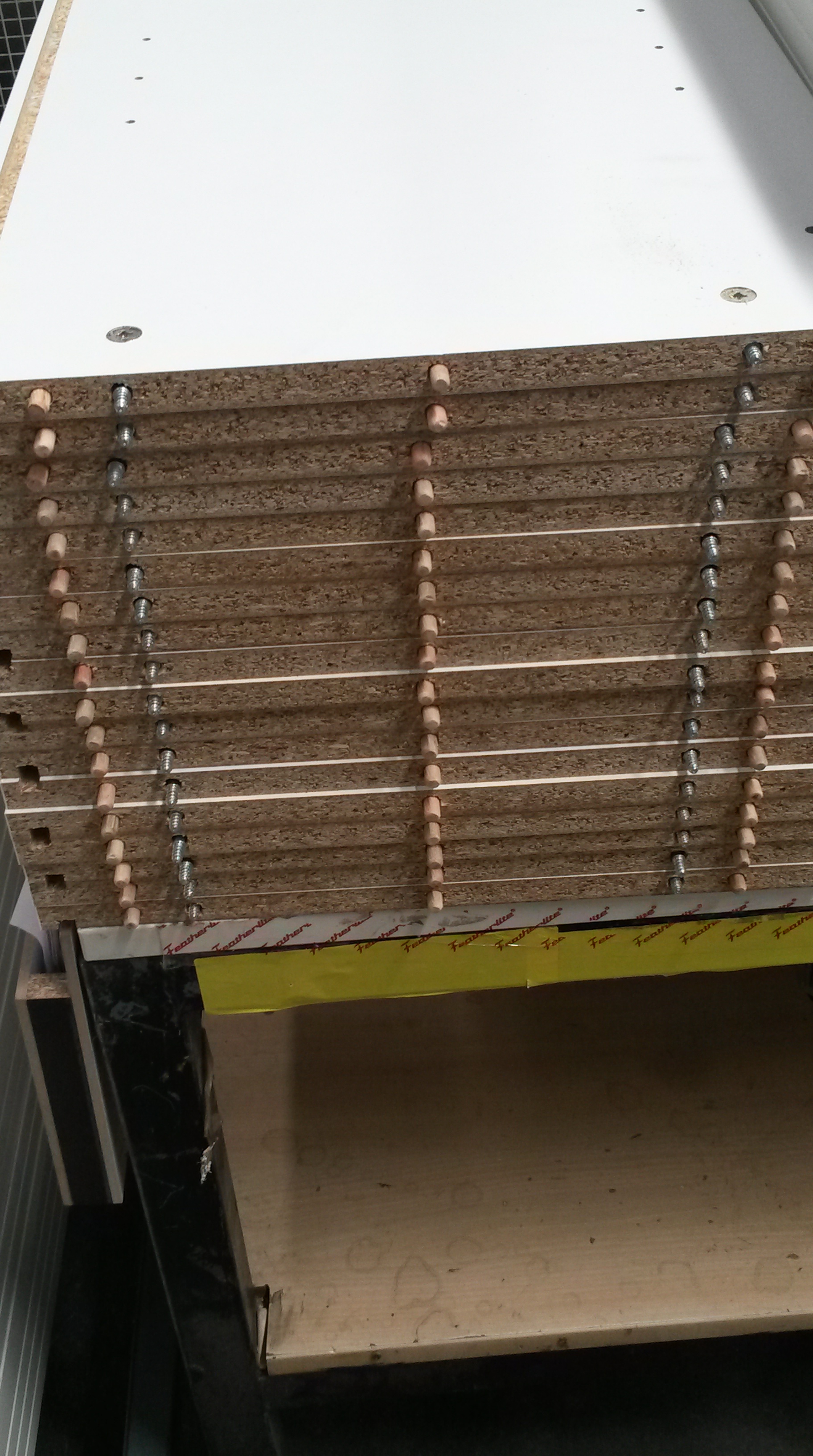
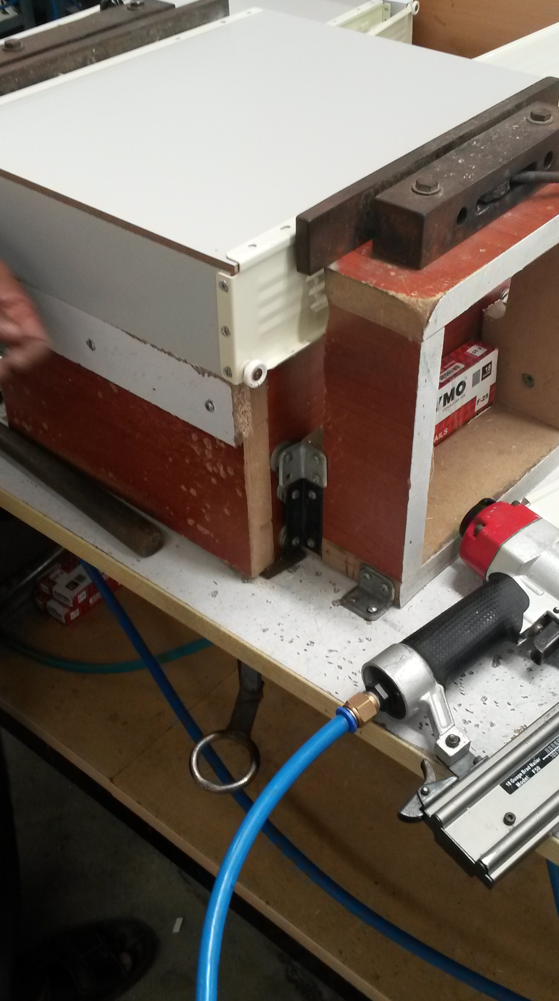
Step 5: Assembly:
The various parts that have been cut into shape, drilled, edge banded or coated are then assembled manually to create the final product. The assembly of a cabinet is shown below.
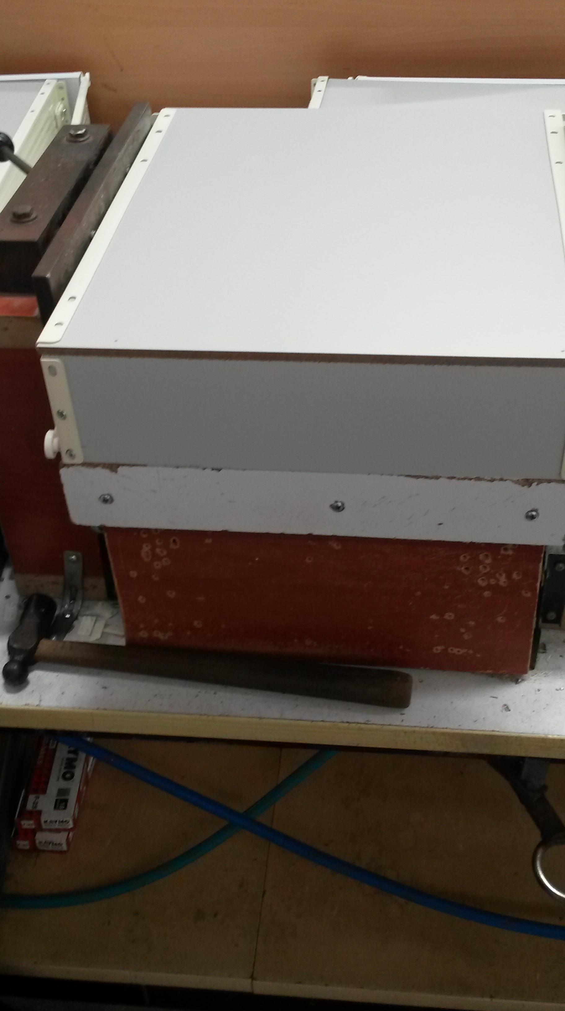
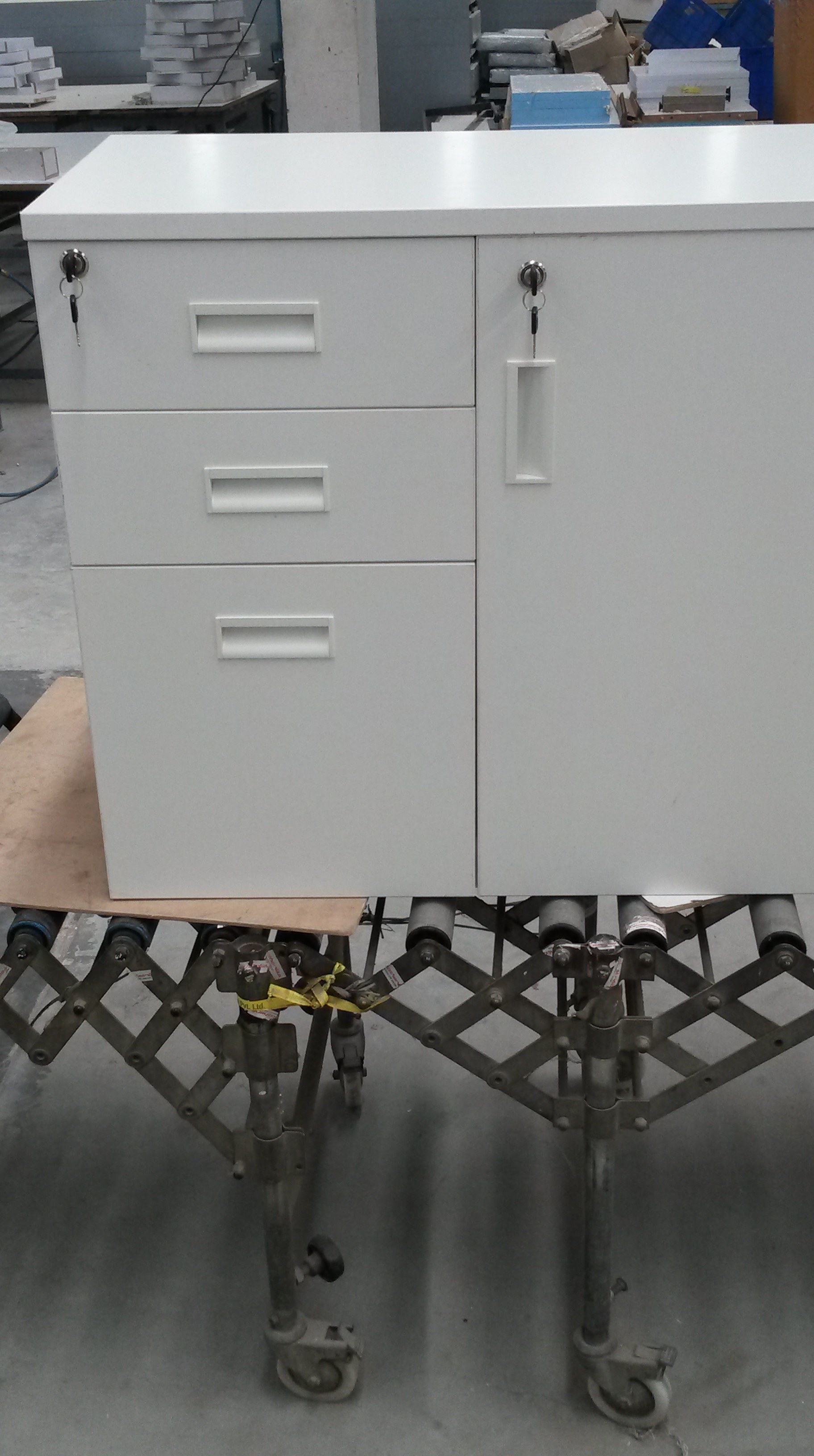
The locks and sliding mechanisms for drawers are procured from other companies and then inserted where required.
More complex furniture can be assembled too, as shown below:
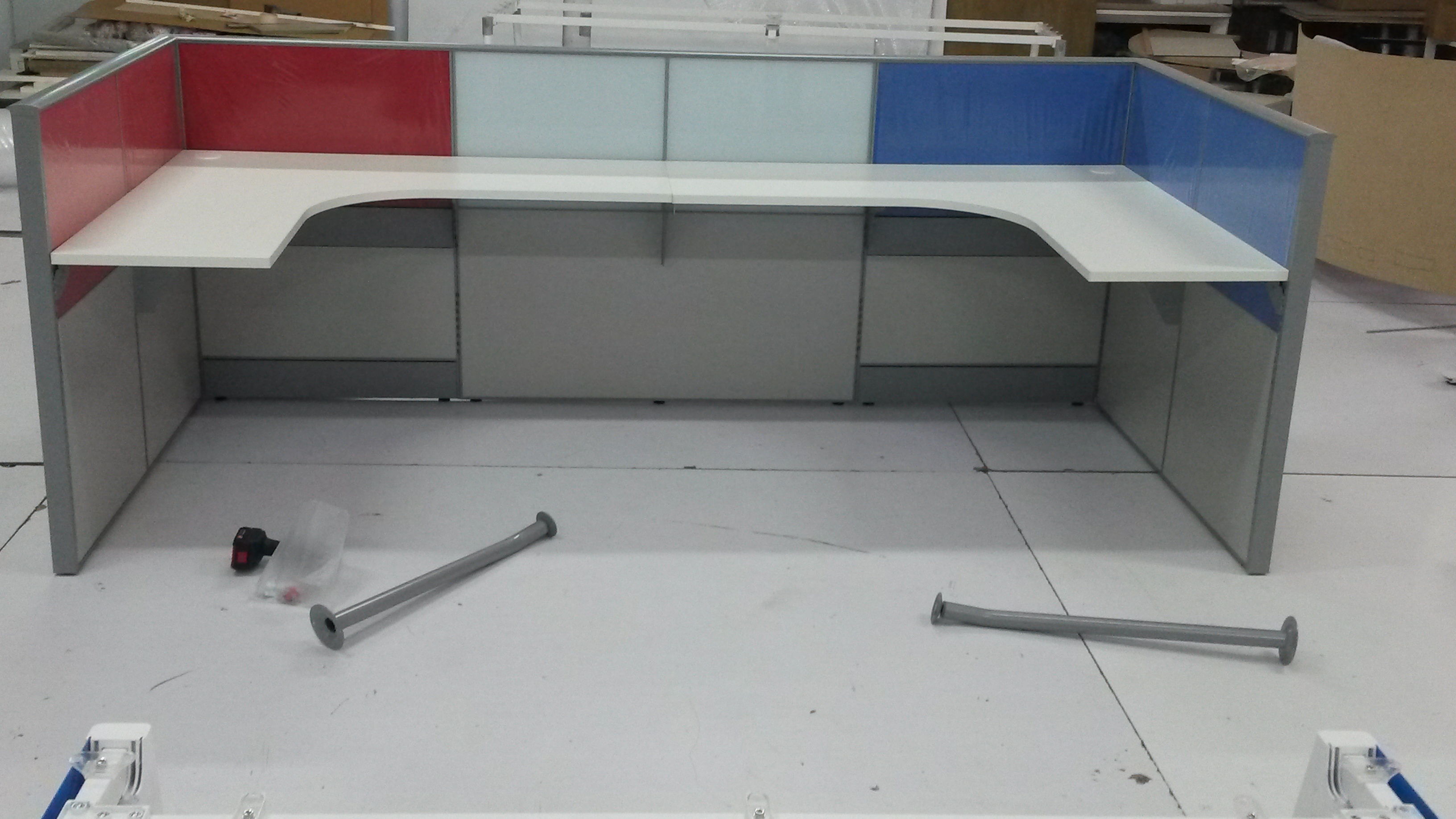
It is the versatility of the CNC’s allow an extremely large number of shapes to be cut and assembles together in any way required, whether it is to produce a cabinet or desk.
Bread
BlogHere’s a look at how bread is made at the industrial scale:
Step 1: Sieving:
The flour is passed through a sieve with the use of a motor. The motor and the sieve make up the sieving machine that is shown below.

Sieving makes the flour fine and removes any impurities in the flour.
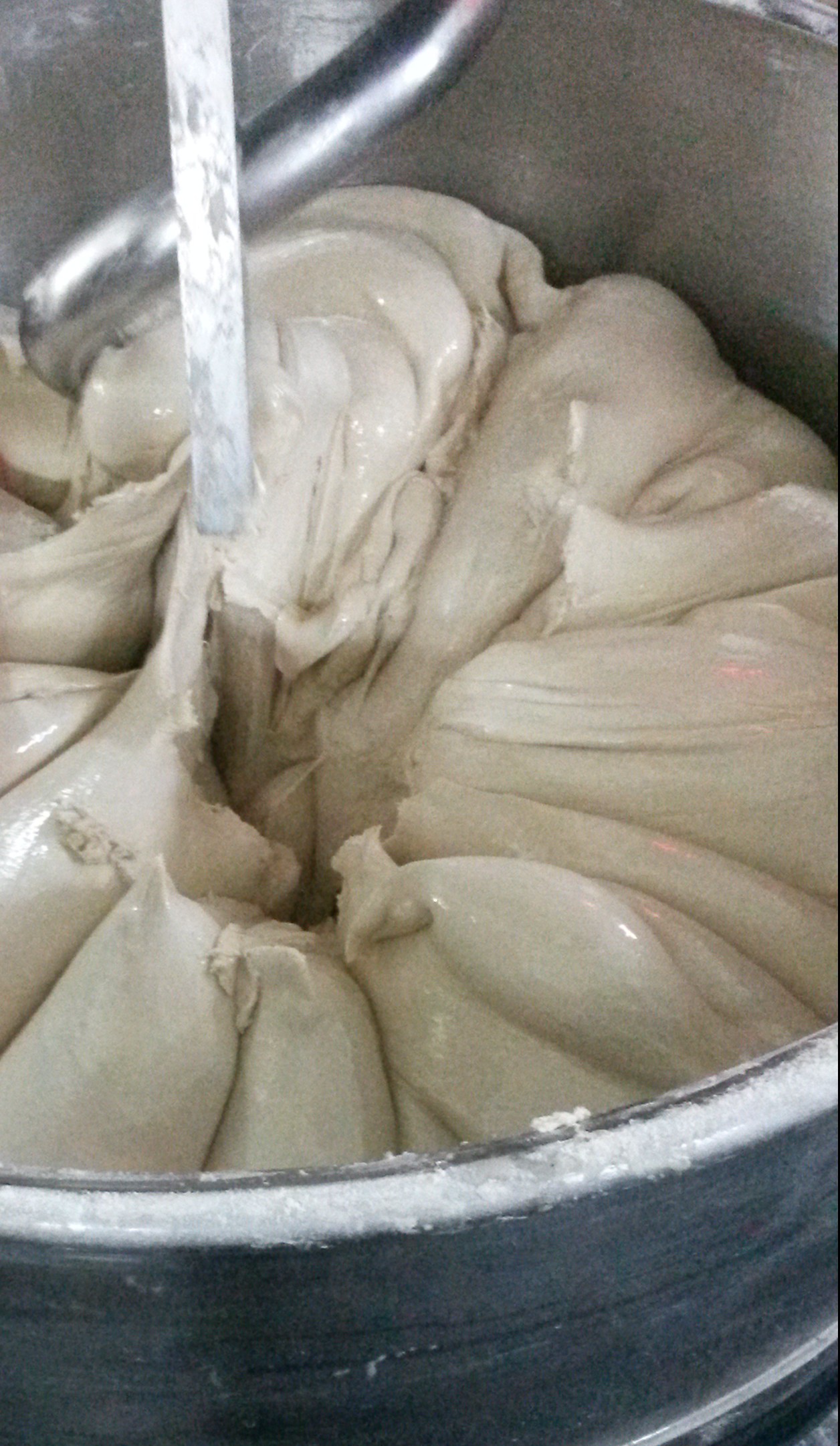
Step 2: Mixing:
The ingredients to make the bread, including flour, water, oil and yeast, are mixed together in the desired ratio (depends on the bread being made), as shown below.

Interestingly, cold water is used in the mixing process. This is to slow down the anaerobic respiration of yeast (see step 4) and prevent the bread to rise too fast.
After a while, about 20- 40 minutes depending on the quantity of ingredients, the water and oil bind themselves to the flour producing the dough of the consistency shown in the image below.
Step 3: Slicing and Rolling:
The dough is then transferred to a slicer and roller, the workings of which are illustrated in the video below:
As seen, dry flour is added to the dough to prevent it from sticking to any of the machinery.
After the dough is rolled it gets put into the bread moulds and into the proofing room.
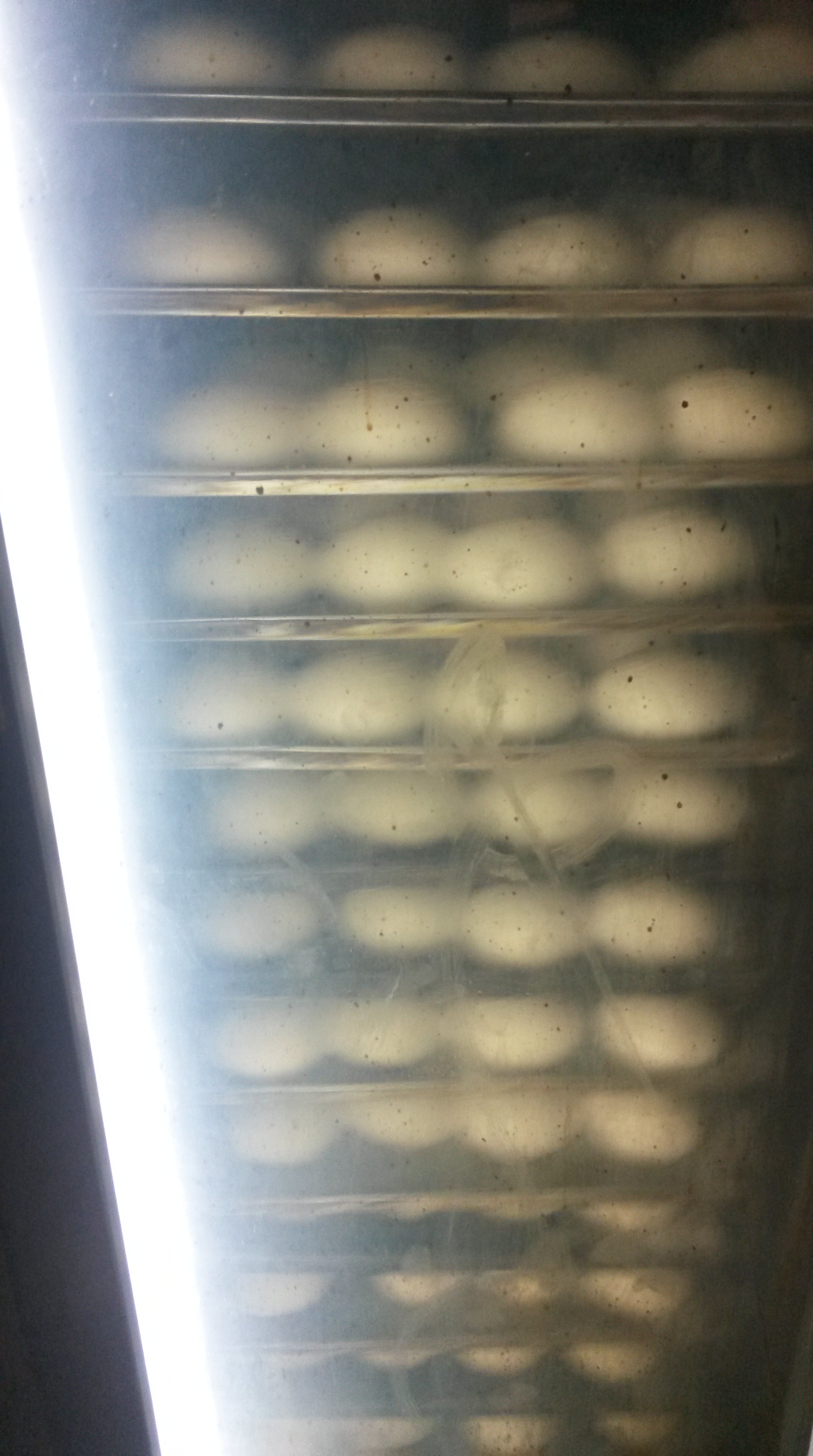
Step 4: Proofing:
Proofing refers to the stage where the yeast is allowed to ferment and dough to rise before being put in the oven. It is put in the proofing room, which has a high temperature of about 60- 80 degrees Celsius, with the moisture level in the room regulated. The image below shows the proofing room:
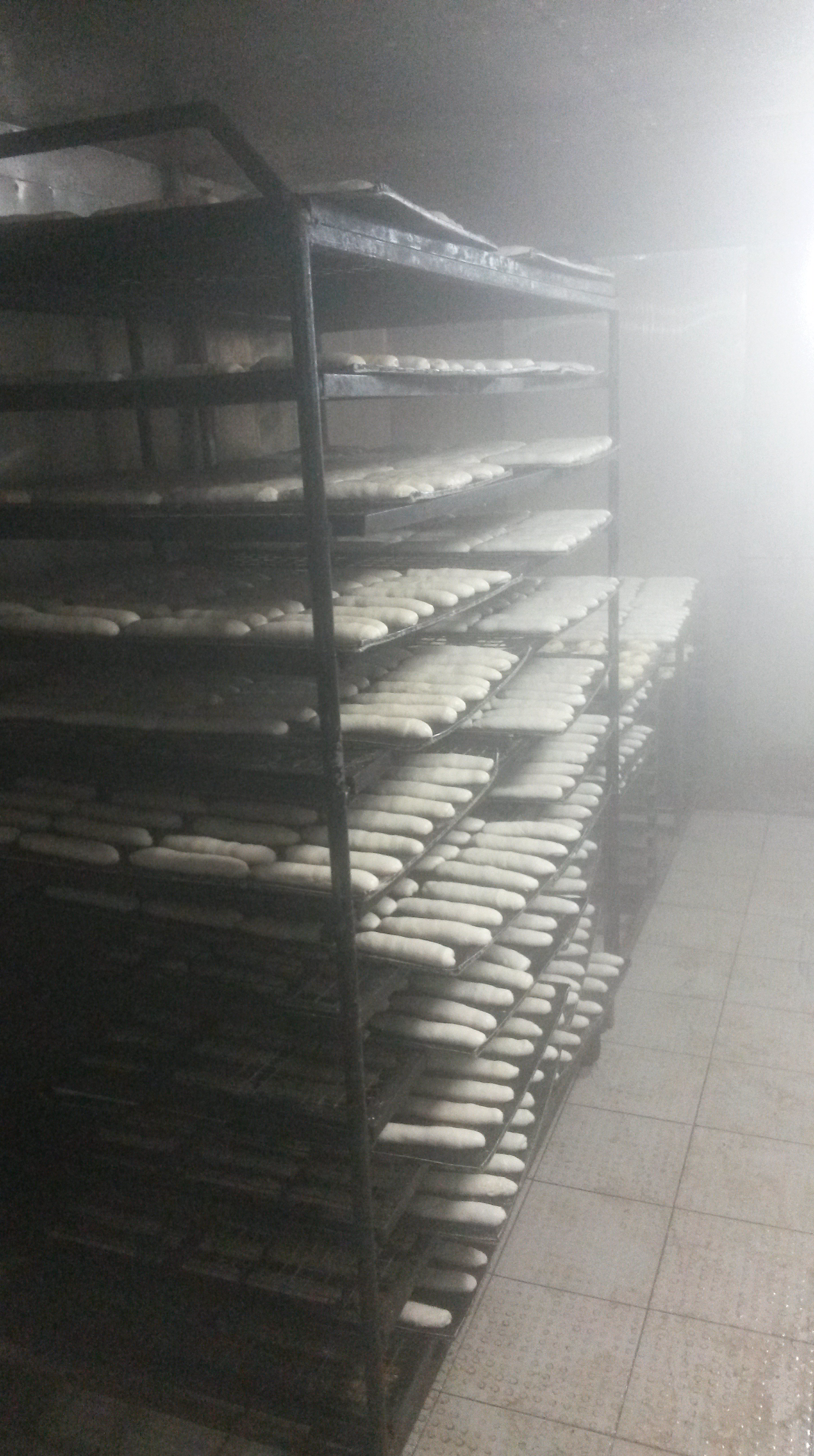
Fermentation and the rising of dough occur due to the anaerobic respiration of yeast, i.e., the conversion of sugars to produce energy in the absence of oxygen in contrast to aerobic respiration which happens in the presence of oxygen.
The first step in both in aerobic and anaerobic respiration is glycolysis, which converts glucose to pyruvate, according to the simplified equation given below:
C6H12O6 —-> 2 CH3COCOO– + 6 H+
In yeast, the pyruvate is then converted to an acetyldehyde, using the enzyme pyruvate dehydrogenase, as illustrated by the equation below:
CH3COCOO– + H+ —-> CH3COH + CO2
The carbon- dioxide produced in this reaction is responsible for the bread rising.
Finally, the acetaldehyde is converted to ethanol, using the enzyme alcohol dehydrogenase, according to the equation below:
CH3COH + 2H+ —–> C2H5OH + Energy
Overall, the simplified equation for fermentation in yeast during proofing is:
C6H12O6 ——> 2 C2H5OH + 2 CO2 + Energy
Humans, on the other hand, do not contain the enzymes yeast does and therefore produce lactic acid during anaerobic respiration instead of ethanol.
After the fermentation of yeast starting to occur during proofing, the dough can finally be put in the oven, to finish the fermentation process.
Step 5: Baking:
The proofed dough is put in large industrial ovens, as seen in the image below:
The temperature must be controlled in the oven precisely to ensure the optimum activity of the enzymes are reached. Enzymes, as the graph below shows, work optimally at a particular temperature. If the temperature is too high their active site gets denatured and if the temperature is too low, not enough energy is available, reducing the rate of reaction.
The high temperature in the oven also evaporates the alcohol produced during anaerobic respiration, and this the final bread does not have a significant alcohol content.
Step 6: Cooling:
The bread is then left to rest for about half an hour, before it can be cut, as the image below shows:
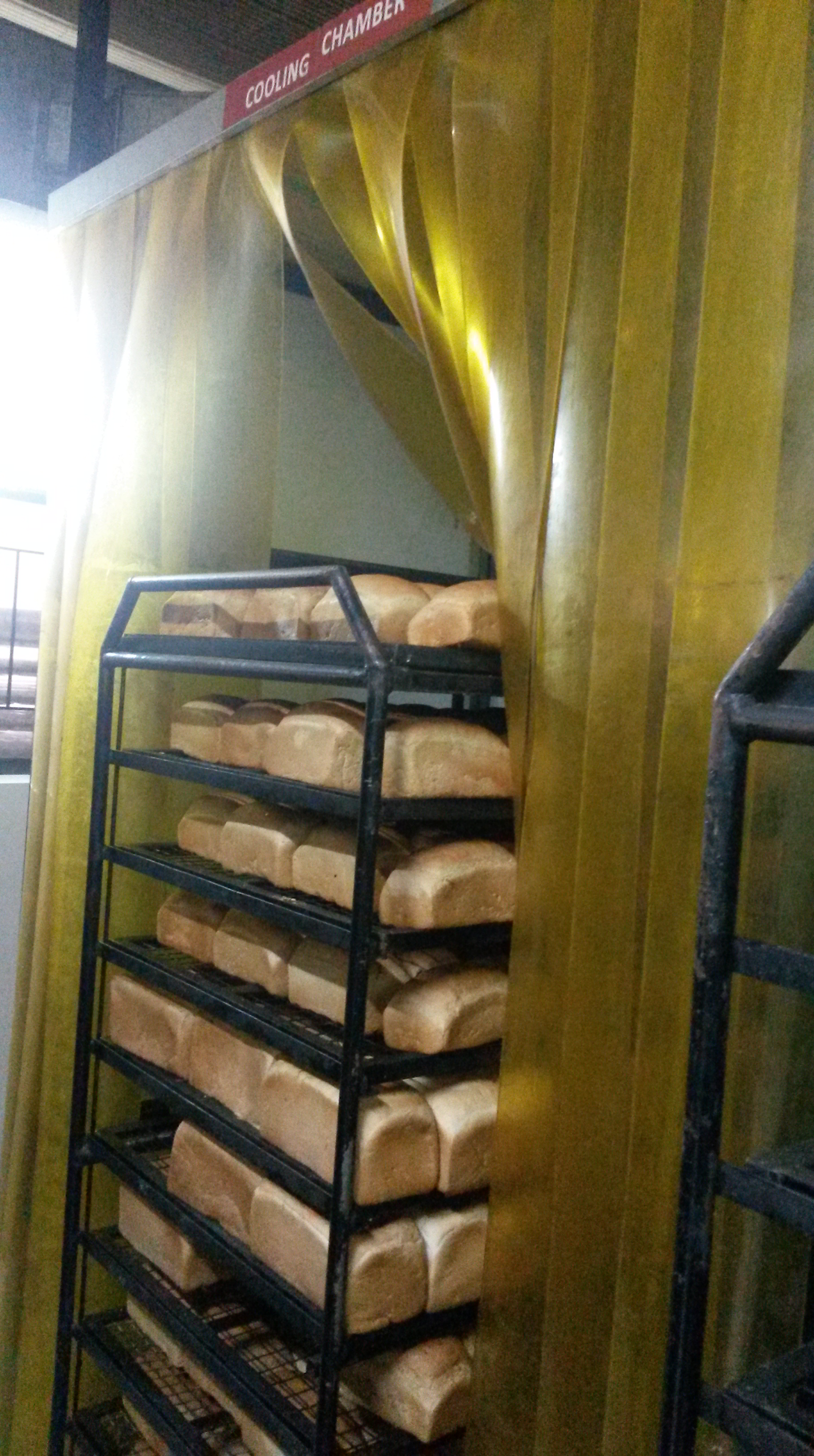
During the cooling process, the bread continues to bake and any moisture evaporates, without which the bread would have too much moisture.
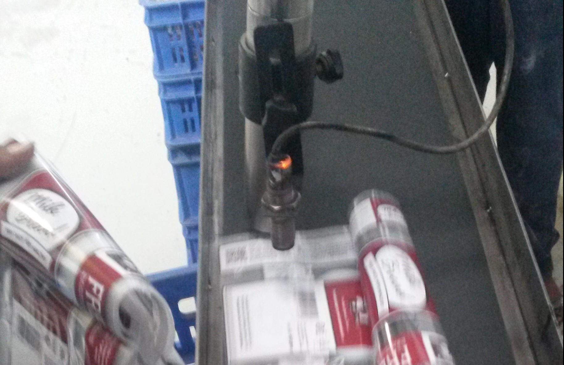
Step 7: Slicing and Packing:
Finally, the loaves of bread are sliced using the machine shown below. The blades move back and forth while, the bread proceeds down the ramp, cutting the bread.

As bread is a perishable good, the manufacturing date must be printed onto the plastic packet. In order to do this there is a computer controlled machine, that changes the date everyday and prints in on the packets, as shown below:
Finally, the cut bread is packed into plastic packets manually and ready for transportation.

Gear Boxes
BlogStep 1- The Raw Material:
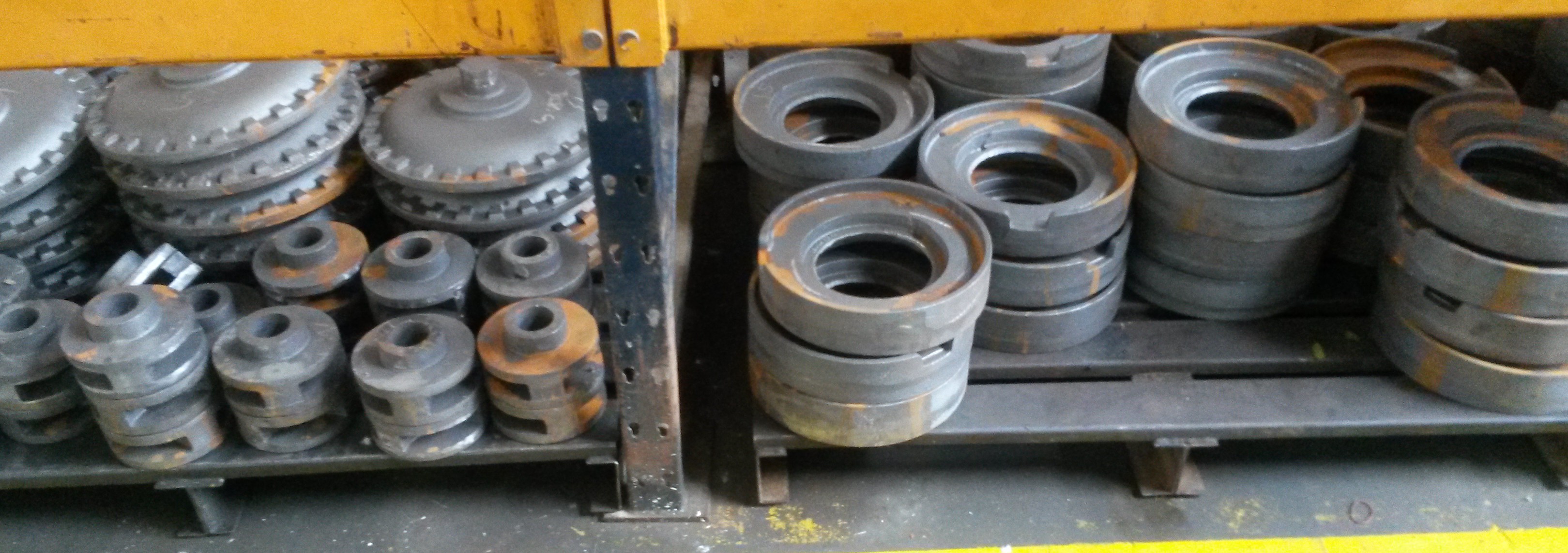
The primary raw material used is cast iron. The iron ore (Hematite) is chemically reduced to Iron in a blast furnace, where coke (carbon) acts as the reducing agent.
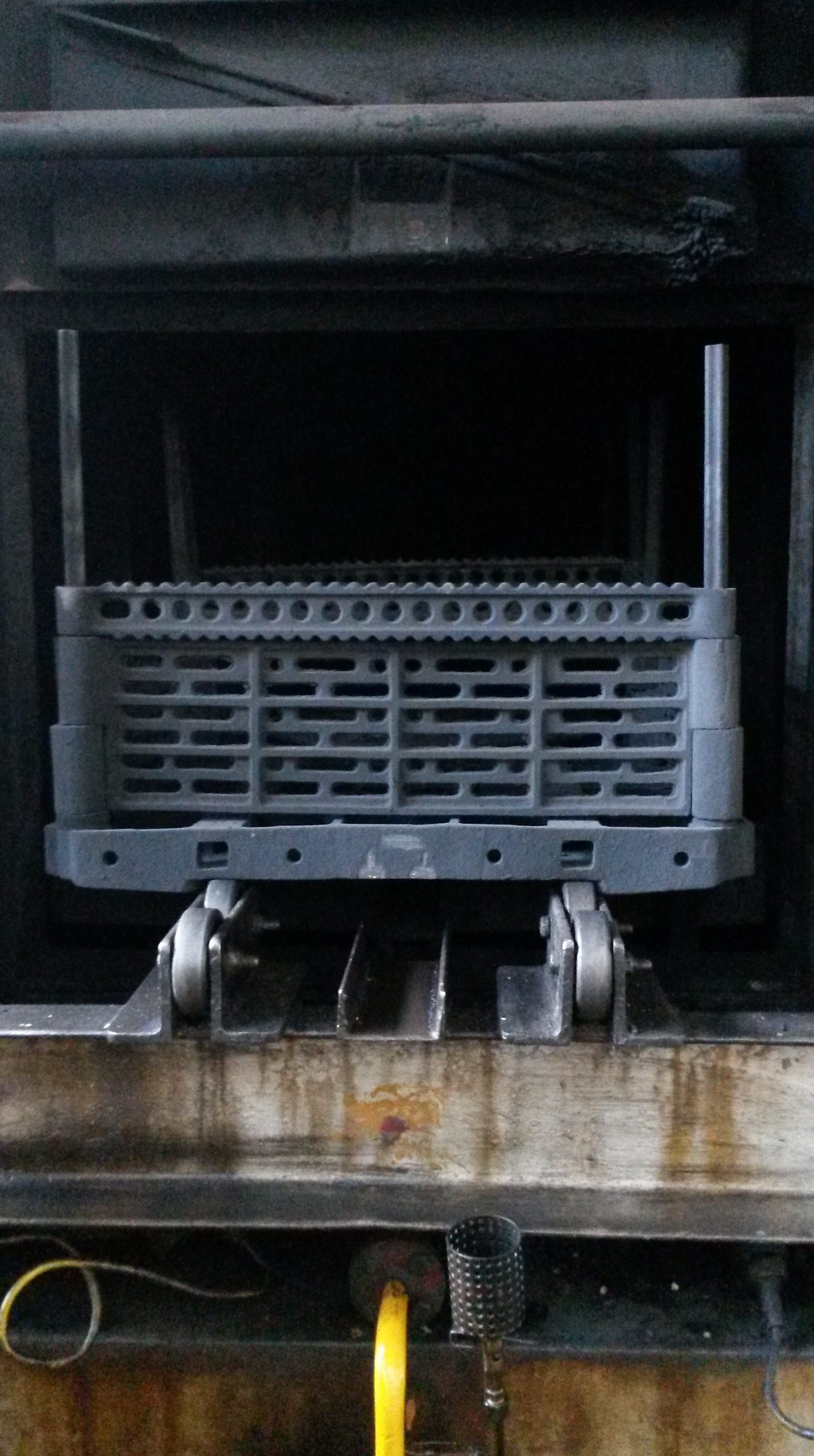
The molten iron that is produced is then put in a mould to produce the rough shape that is required by a part in the gear box. It cannot be moulded into the exact shape, as the level of precision required is too high. The raw material for the gear box manufacturer, i.e., roughly moulded cast iron is shown in the picture below.
Step 2- Heat Treatment:
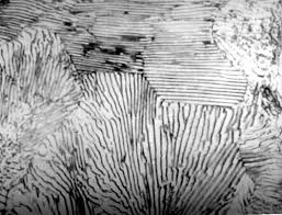
The metal parts that go in the gear box have to undergo a lot of wear and tear. Therefore, it is essential that the metal is hard, but not brittle. The original cast iron is in the form of Pearlite, which has hardness of a maximum of 400 Brinell (unit of hardness). Pearlite, as the image below shows has relatively large crystals which makes it less brittle, but not hard enough.
To increase the hardness of the metal (so that the parts in the gear boxes are less prone to wear and tear), the parts undergo heat treatment.
a) Hardening:
In the same way that graphite transforms into diamond under the influence of extreme heat and pressure within the Earth, metals too can be hardened to change their properties. The cast iron is heated to 850°C for two hours in a furnace. The heat increases the energy of the metal atoms, allowing them to rearrange themselves. Gases like Nitrogen and Methanol are also, in small quantities put into the furnace, which diffuse into the metal, increasing it’s hardness. Limestone is also added to the blast furnace to take away the impurities present.
Following this, the metal is dipped in oil for cooling, so the atoms slow down and form crystals. Oil is used instead of water because with water, the crystals would form too quickly, and would be too small. This would make the metal extremely hard, but too brittle. Oil, on the other hand, minimizes how brittle the metal becomes while increasing hardness.
The metal is then washed and tempered.
b) Tempering
The metal is heated again, this time to approximately 620°C for 3 hours. This results in another rearrangement of the metal atoms to reduce any brittleness caused during the hardening process.
This time the metal is allowed to cool in the atmosphere. This ensures extremely slow cooling, which in turn ensures the crystals formed are not too small and brittle.
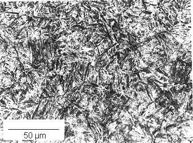
The final result of the heat treatment is the conversion of Pearlite to Martensite, a stronger metal. Martensite has a hardness of up to 700 Brinell, nearly double that of Pearlite. The structure of Martensite is shown below, and it visibly has smaller crystals than that of Pearlite, illustrating the increased hardness.
Step 3- Machining Of Individual Parts:
Using CNC (Computer Numerically Controlled) Machines, individual parts of the gear boxes are machined to the precision of 0.01 mm. In the machine, there is a holder for the roughly moulded cast iron, and on the other side of the machine, there is a rotating piece of equipment that is fitted with tools. The pictures below show these.
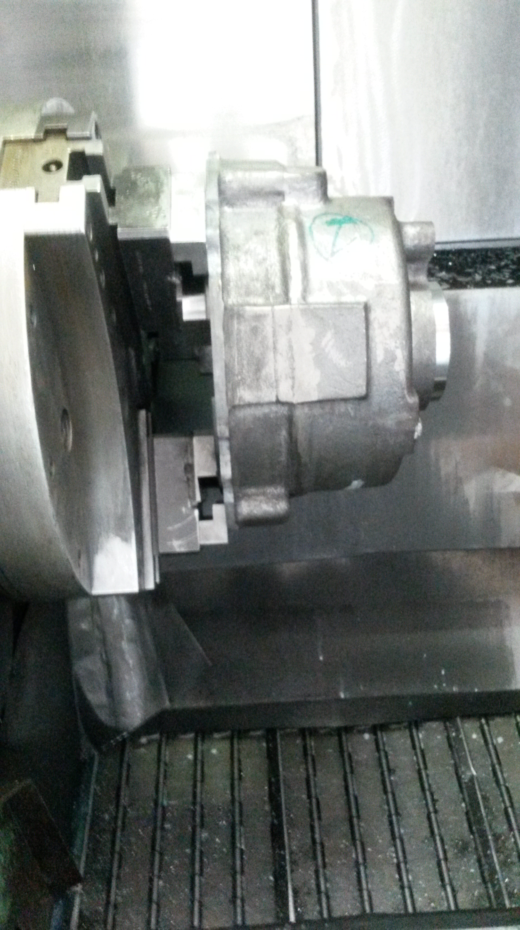
The movement of this equipment is programmed, using imaginary x, y and z axis coordinates. For instance, tool number 1 could be instructed to move to coordinate (2,1,2) [2 unit on the x axis, 1 units of the y axis and 2 units on the z axis]. The code would also include the time that the tool needs to spend there, before making another movement. To machine an individual part, hundreds or even thousands of these instructions need to be coded and then fed into the machine. The images below show the machining process in action.
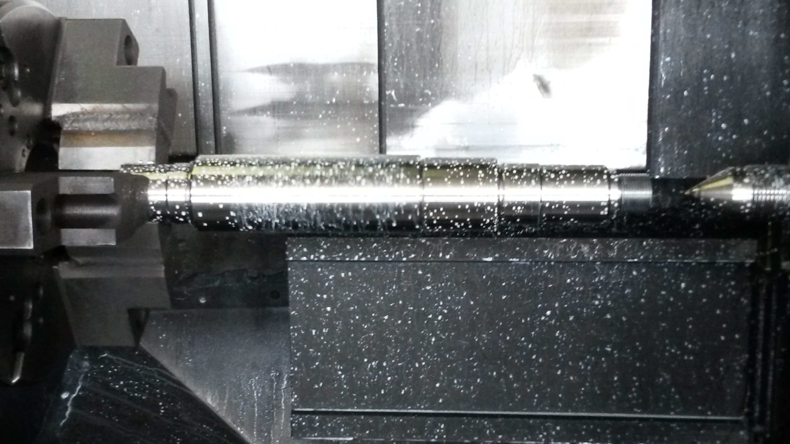
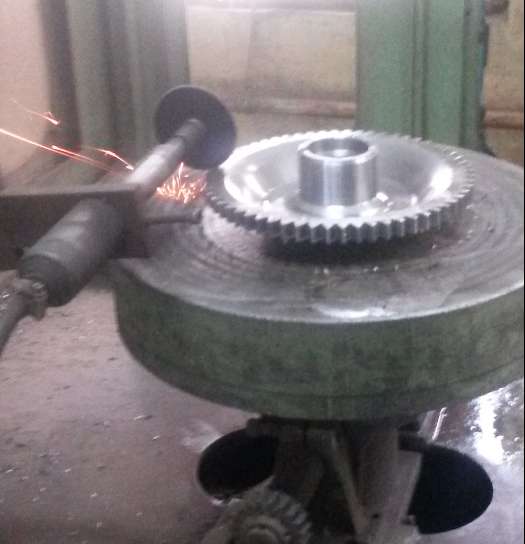
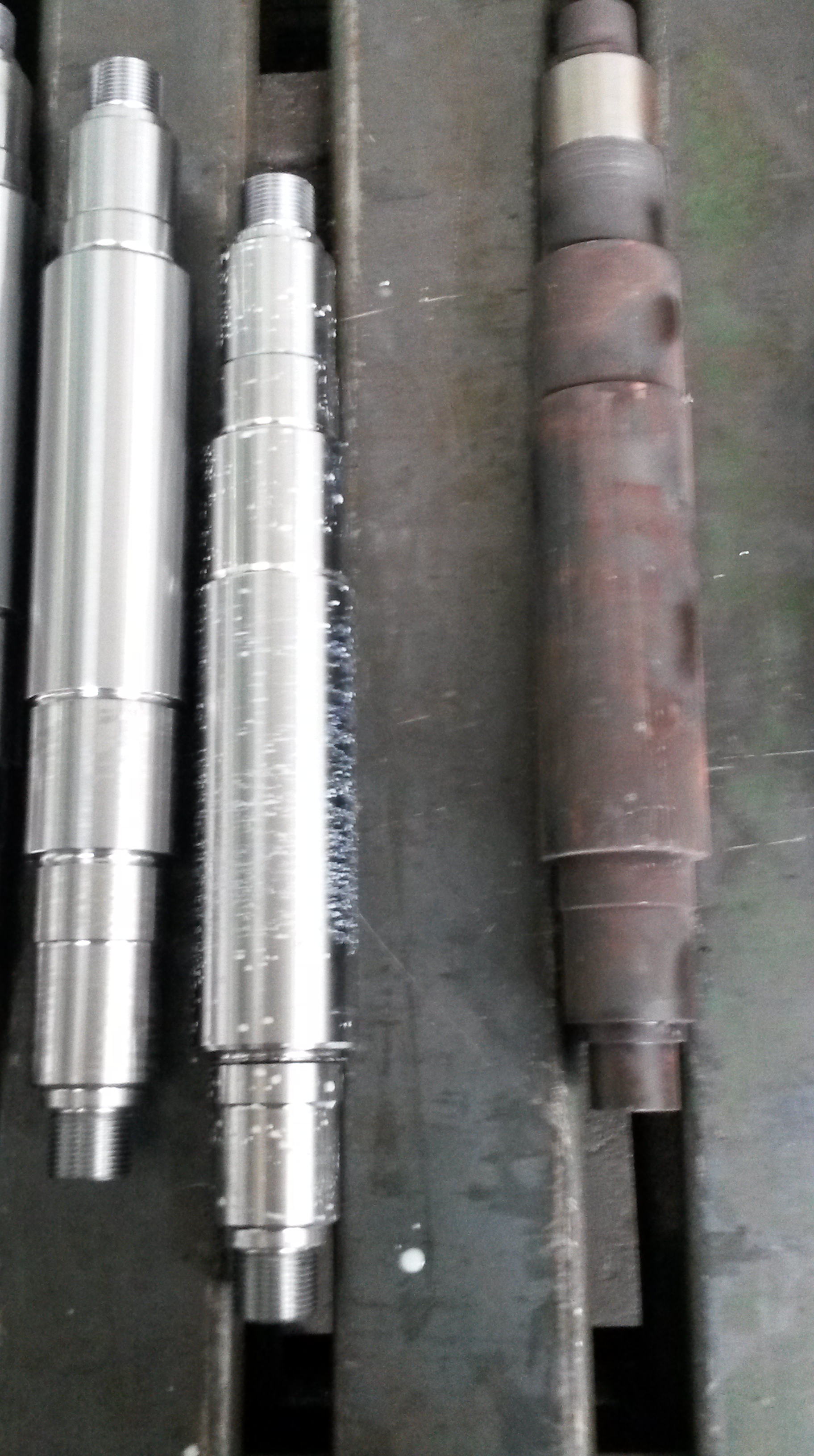
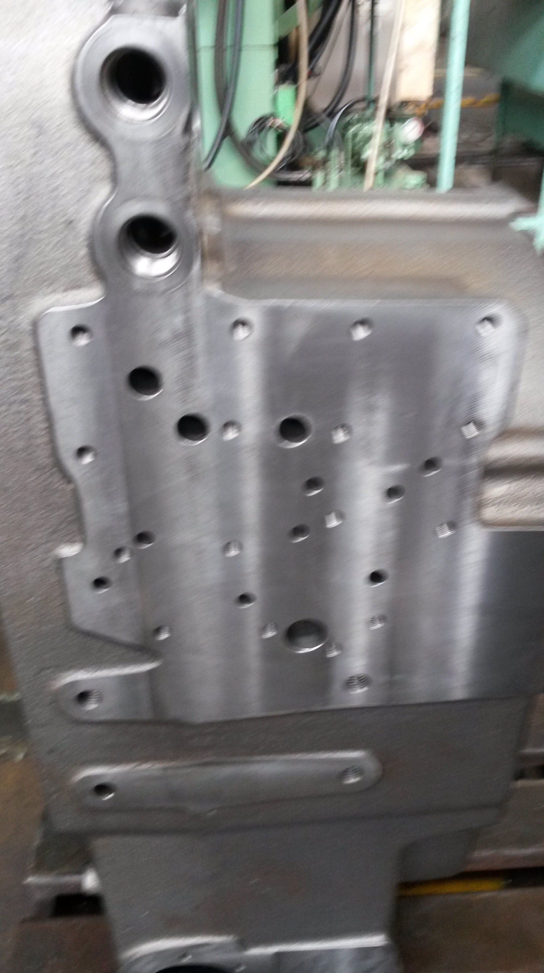
The white liquid being sprayed on the machined part is a coolant. This is necessary as the machining (grinding and cutting) generates a lot of heat. The machined part is a far more refined and precise version of the roughly moulded cast iron. The differences that machining makes are shown in the image below. On the left is the machined part and on the right is the original cast iron moulded part. Machining performs a variety of functions, from drilling to cutting to polishing.

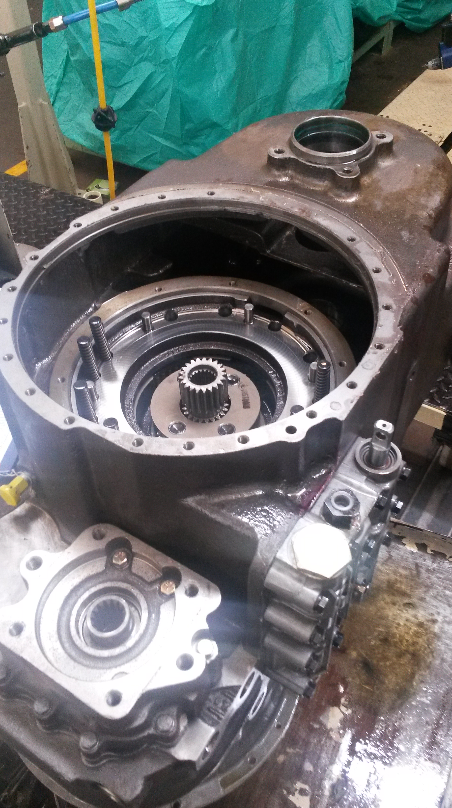
Step 4: Assembly:
All the machined parts are then assembled together, both mechanically and manually.
Step 5: Testing:
a) Dip Tank
The gear boxes are filled with hydraulic fluid and inserted into a tank of water in order to check for any leaks. If any bubbles emerge, leaks are identified.
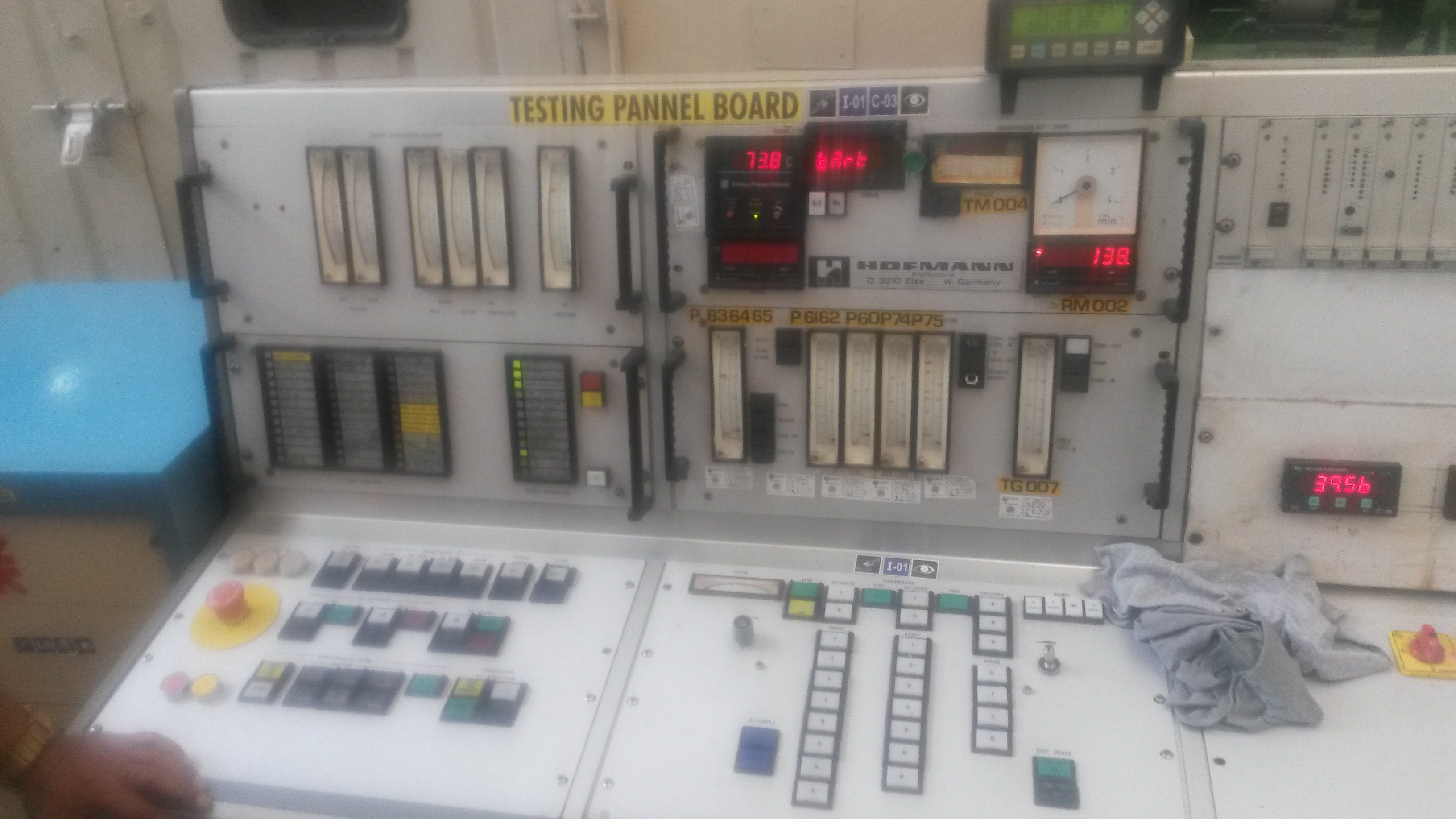
b) Performance Testing
The final check involves connecting the gearbox to an engine to simulate its operation.
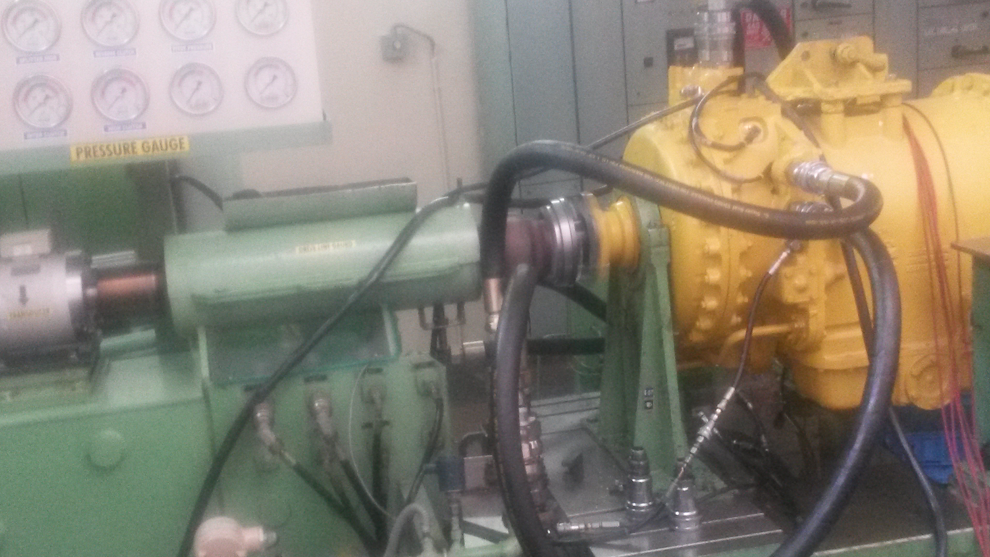
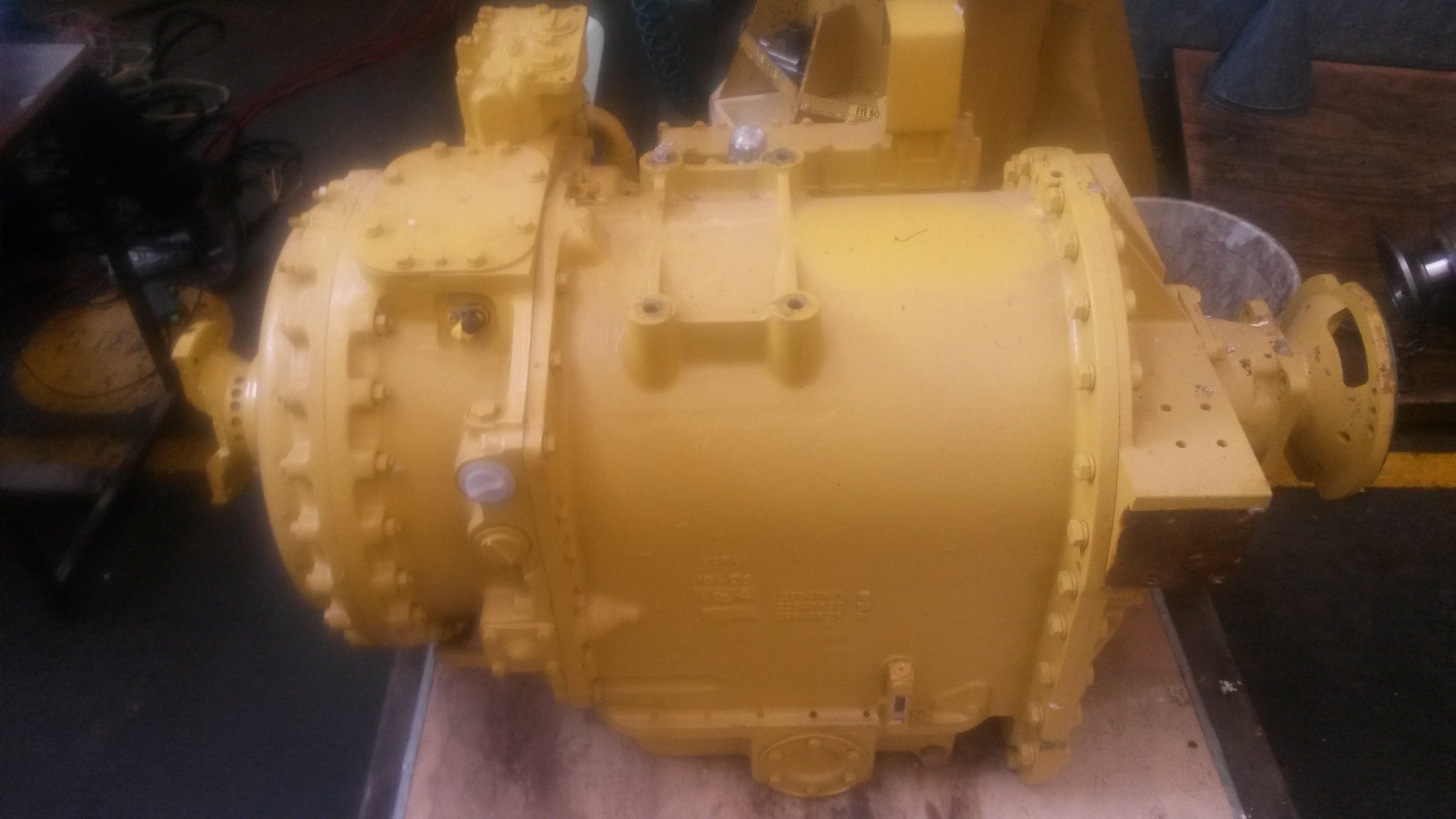
The Final Product:
Consisting of over 150 parts, all individually machined, the gear box is finally produced and ready for delivery.
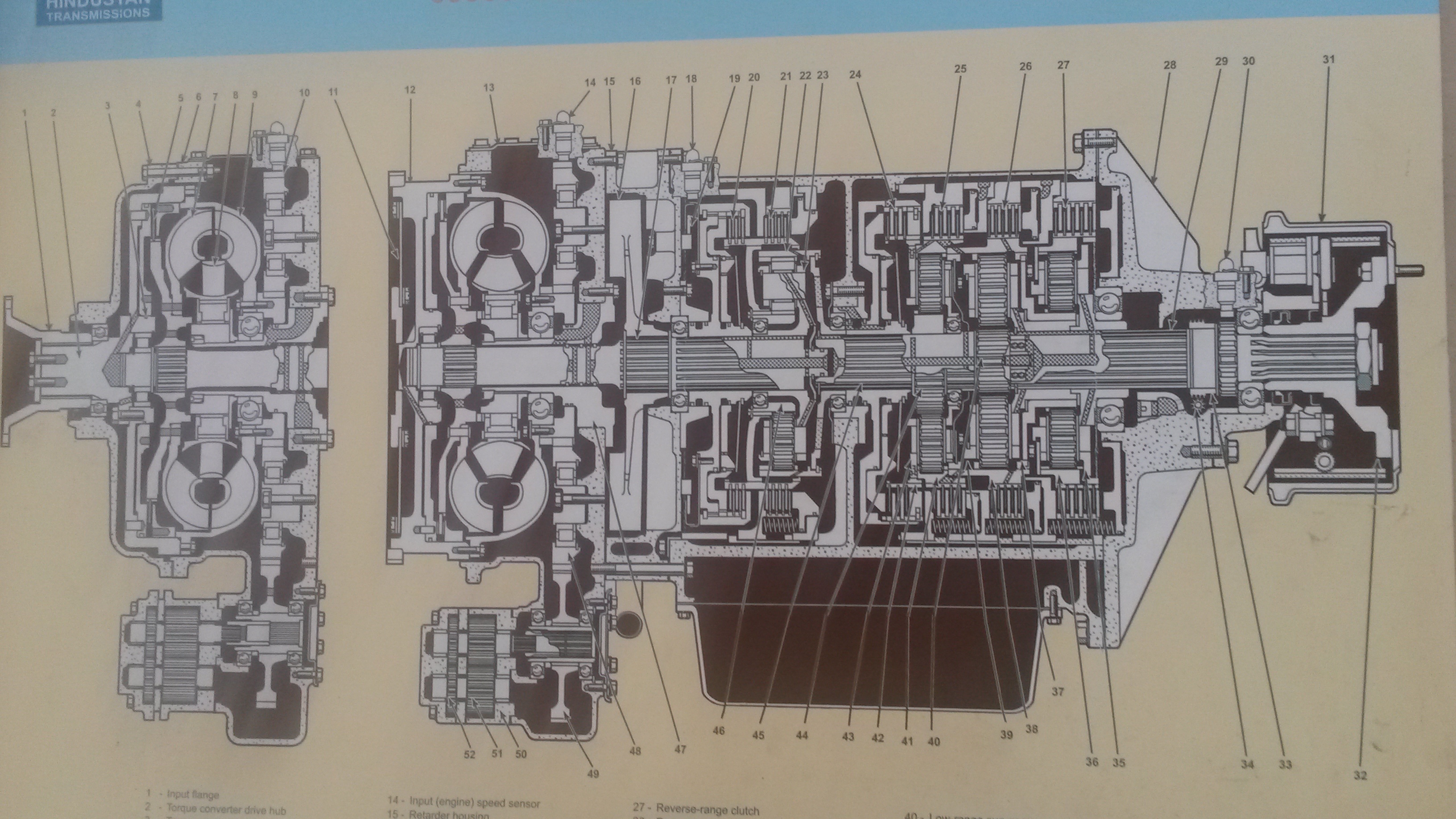
Here’s a look here at how gear boxes work in everyday life!
Cables
BlogI visited a factory that manufactures copper wires and the manufacturing process is detailed below. Enjoy reading!
Step 1: The Raw Material
Cables start of as an 8mm (diameter) copper rod. Copper is cost effective and an excellent conductor of electricity.
Step 2: Reducing the diameter of the wire
While cables are thick, they are actually made by winding many smaller wires together, instead of one thick wire. These are called multi-stranded wires, and make the cable more flexible. Furthermore, multi-stranded wires are better conductors than a single thicker wire because the individual wires have greater surface area. They also provide higher resistance to “metal fatigue”, which is when the material is weakened due to fluctuations in the power load flowing through it.
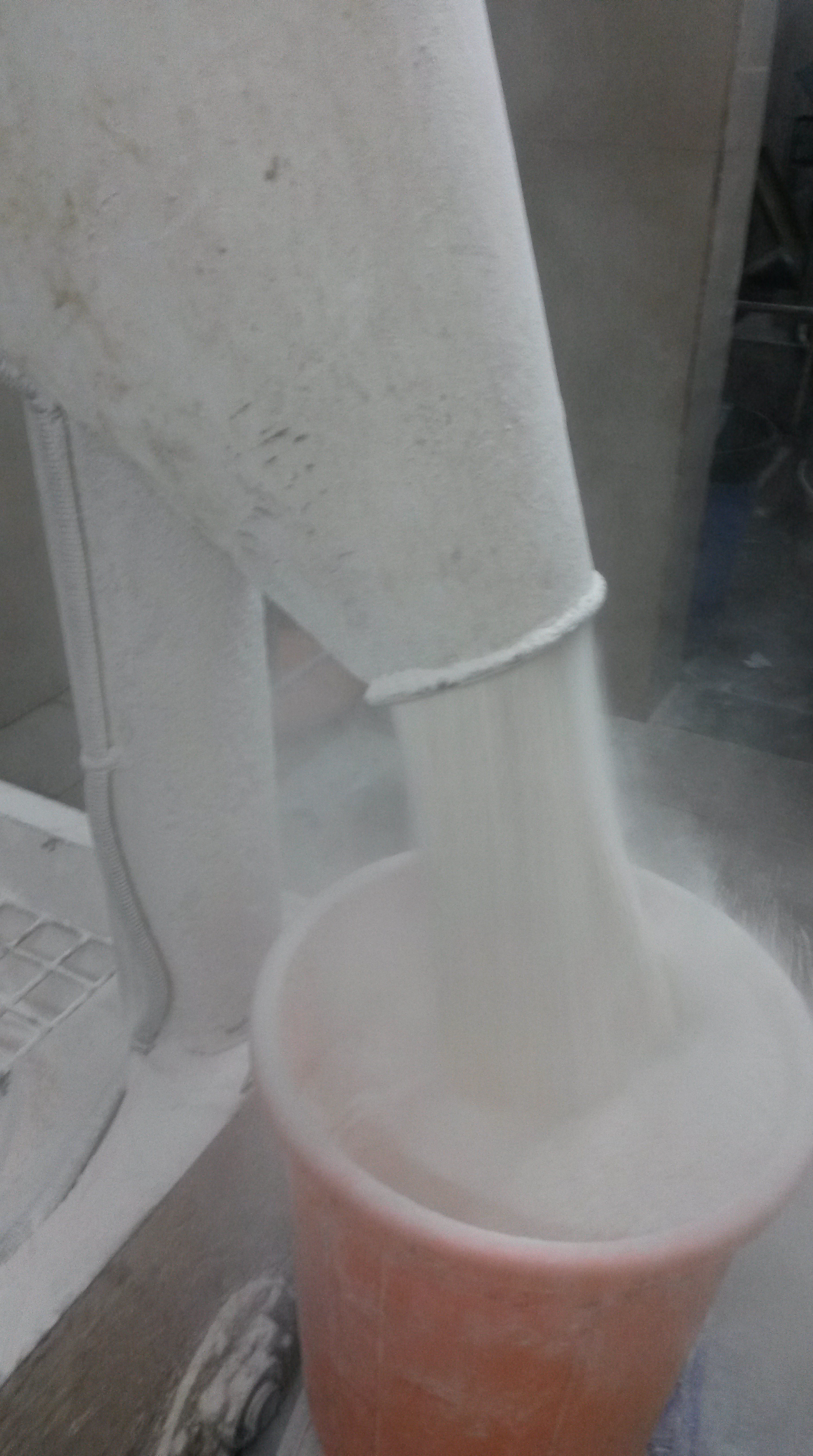
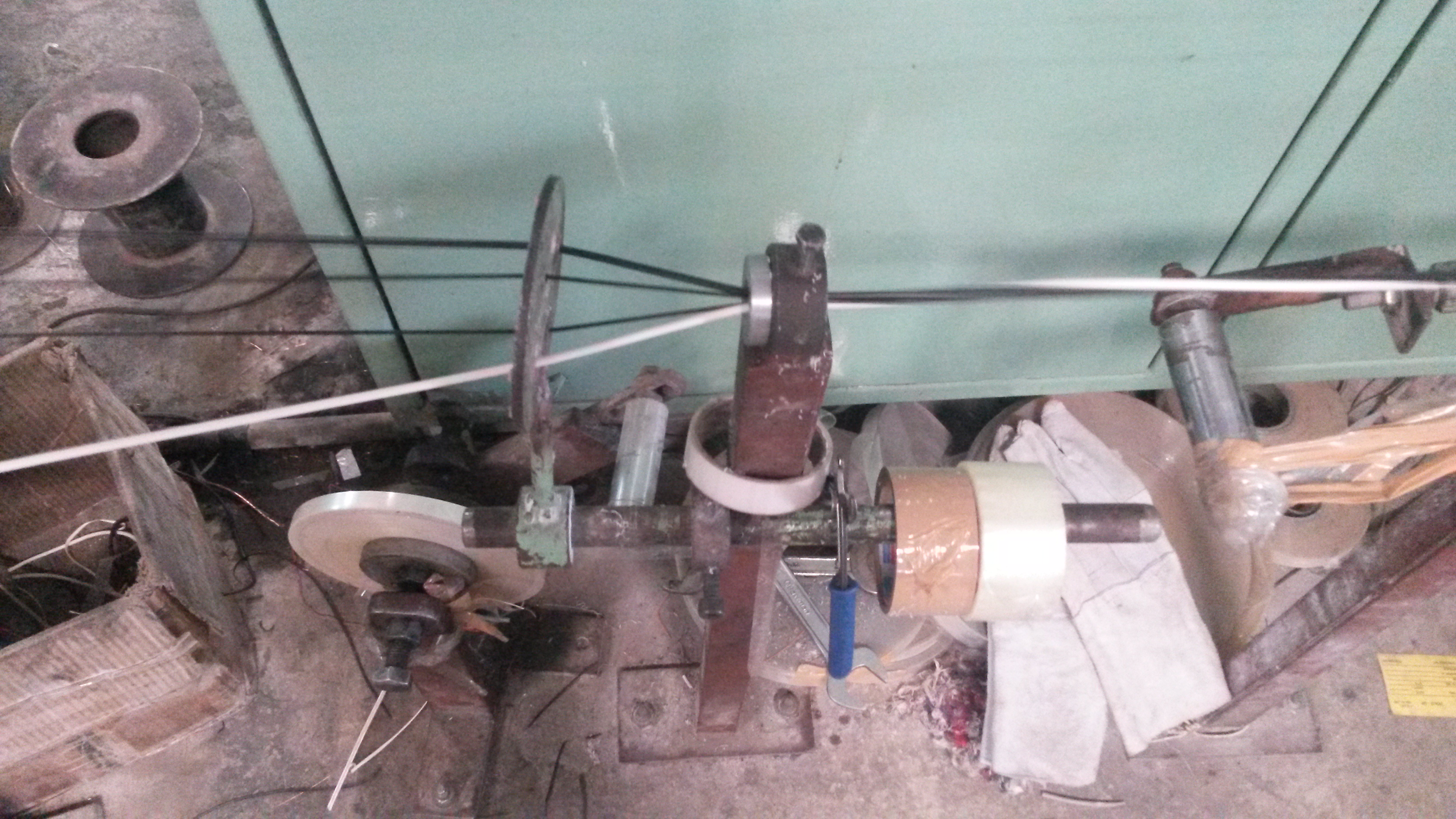
Therefore, the copper wire’s diameter is reduced progressively from 8mm to 4mm to 1.4mm and finally 0.5/0.4/0.3 or 0.1 mm. It is done progressively, as the wire would break if all the required force was applied all at once.
This is done by simply squeezing the wire through a hole of the required diameter, at a slow pace. This generates a substantial amount of heat, so the wire is made to flow through a coolant (the white liquid) and the thinner wire is then wound. These are illustrated by the images below.
Step 3: Annealing:
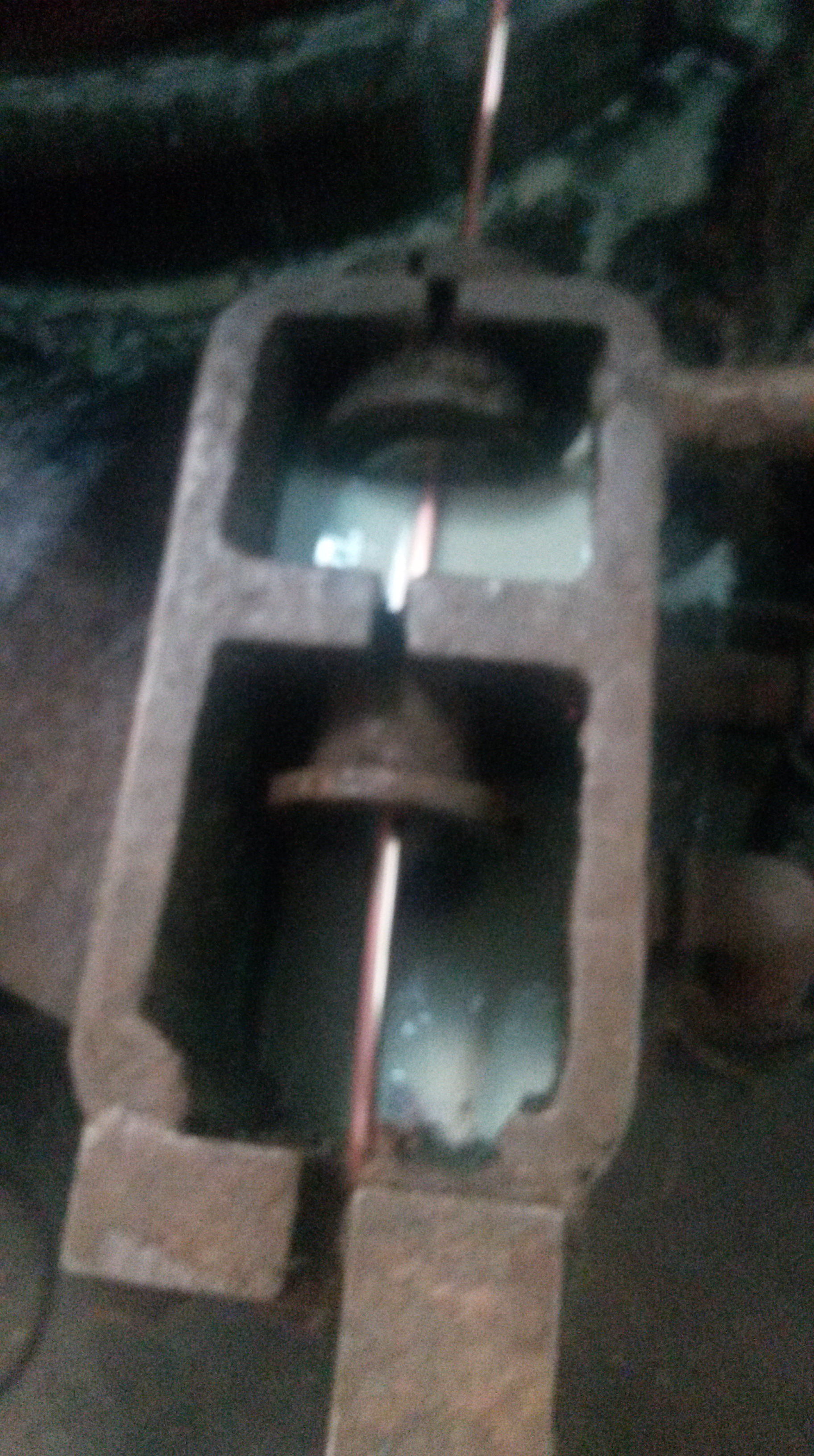
To further increase the flexibility the copper wire, it undergoes a process called annealing, where it is heated to about 400 degrees Celsius under controlled pressure for about 4 to 5 hours in the container shown below.

Annealing increases the copper’s ductility (its ability to be stretched into a wire) as the heat increases the kinetic energy of the atoms, making the material less rigid. The copper is then cooled, which can be done slowly in air, or through “quenching”, where it is cooled quickly in water. Copper retains the properties induced by annealing even when it is quenched unlike other ferrous materials, such as steel which must be cooled slowly for annealing to work.
Step 4: Bunching:
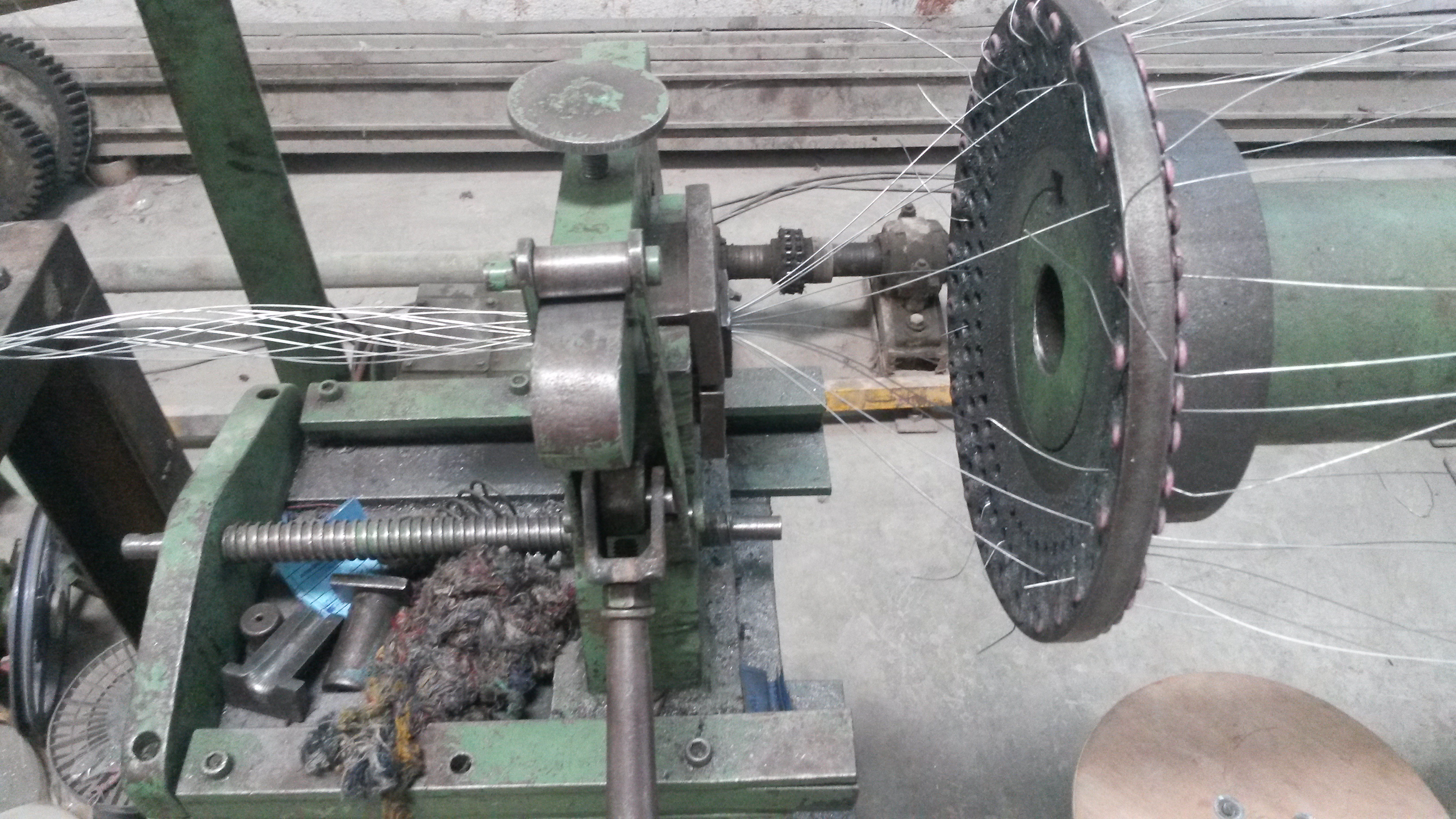
The thin, annealed wires are finally bunched together to create one thick cable by the machine shown in the image below. The machine takes thin wires from several coils and then winds them together. The wound wires are then pushed through a hole which strengthens the bunching to make it permanent.
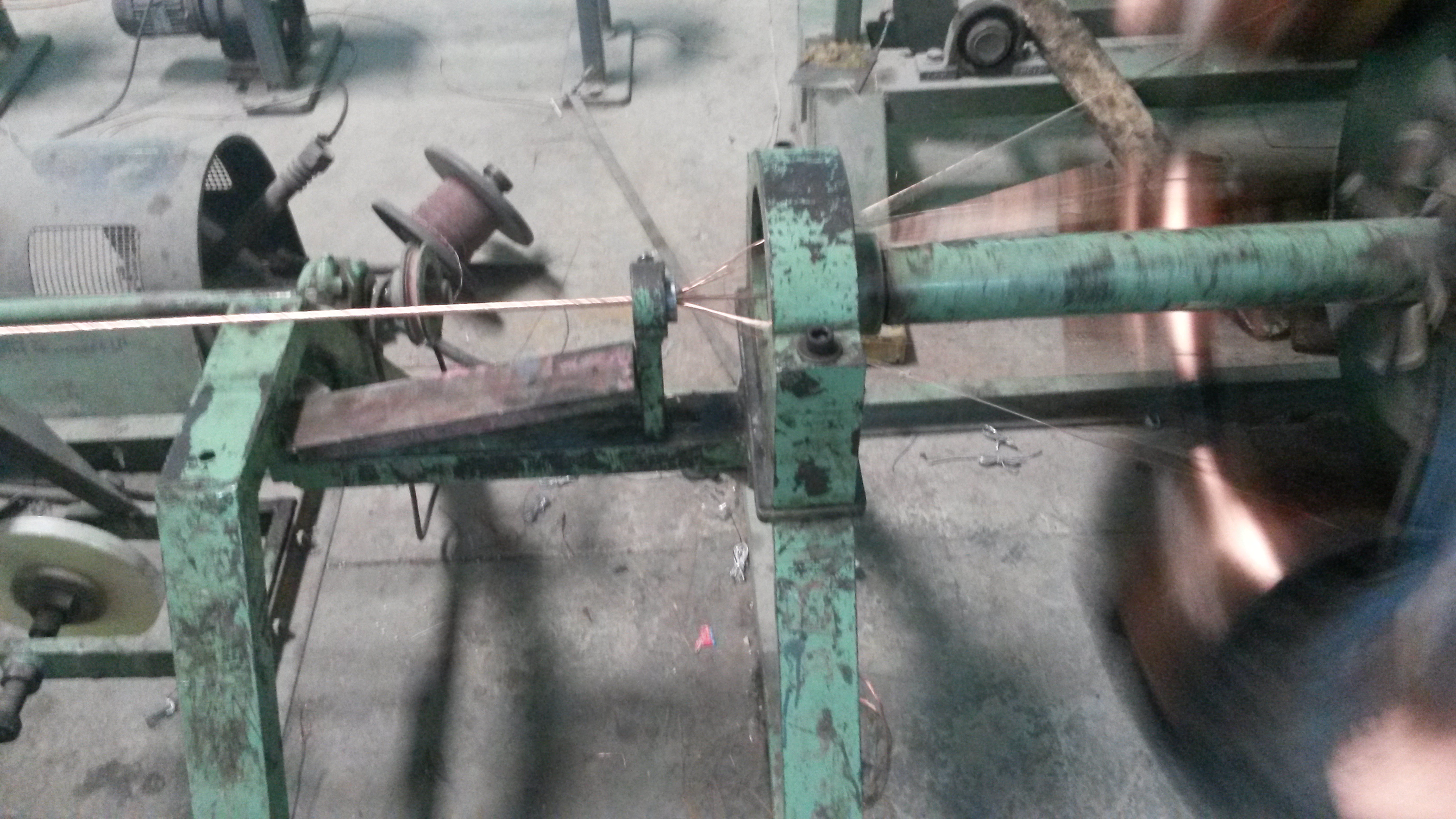
It is essential to have thick cables, as a larger area of cross section results in lower resistance, resulting in the current being carried more efficiently.
Technically:
Resistance = [(resistivity)*(length)] / (area of cross section)
The resistivity of copper is a constant and assuming the length of the cable is also constant, we get:
Resistance ∞ 1/ (area of cross section), i.e., the resistance of the wire is inversely proportionate to the area of cross section.
This YouTube video shows a wire bunching machine:
Step 5: Insulation and Extrusion:
Another essential property of cables is insulation, so that they are safe to use.
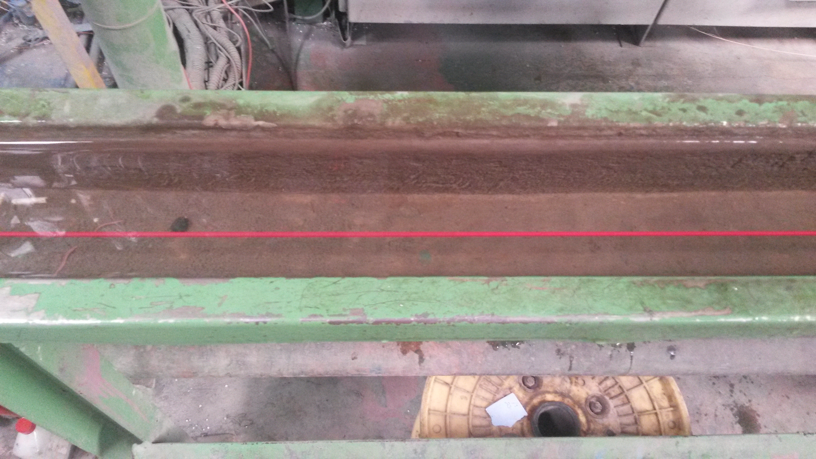
In order to insulate the wire, PVC (Poly Vinyl Chloride) is melted and made to coat the copper wire, as shown in the image below. On the left you can see the un-insulated copper wire and on the right you can see a red coating of PVC (which has flown in from the pipe) on the wire. This process is called extrusion.
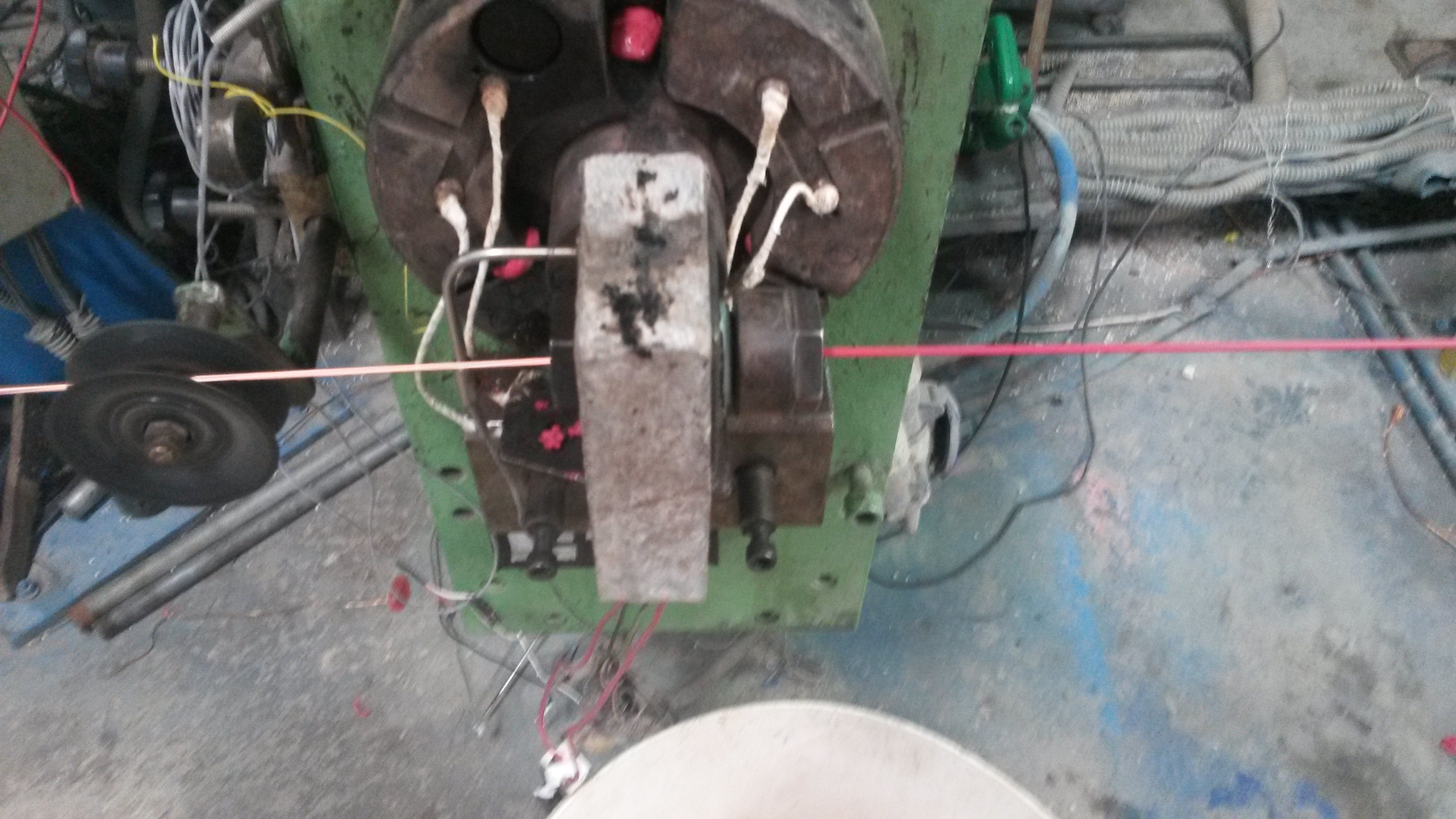
The PVC coated copper wire is then made to flow through water to cool and solidify the PVC, as shown below:
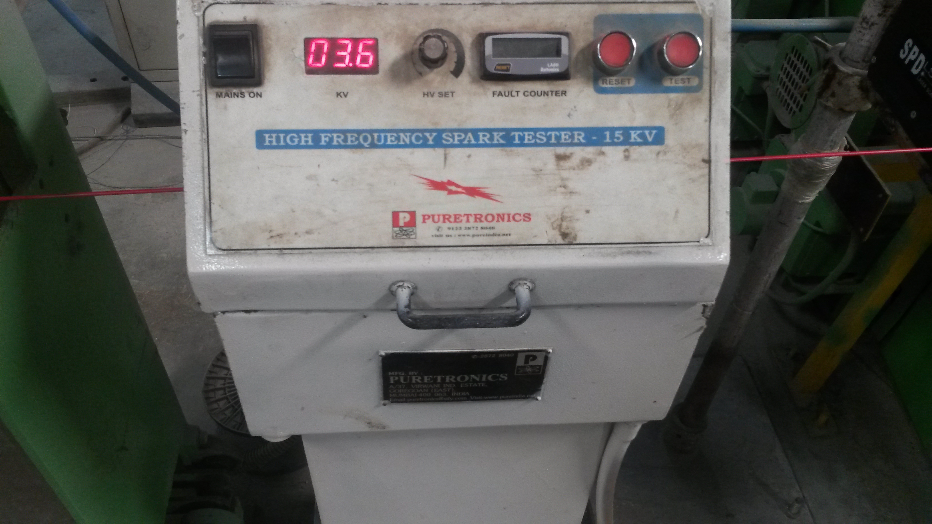
To detect if there are any holes in the PVC the wires goes through a high frequency spark tester.
Often, one layer on insulation is not enough, so many of the insulated wires are bundled together and sometimes even armored with steel, before it is extruded again.
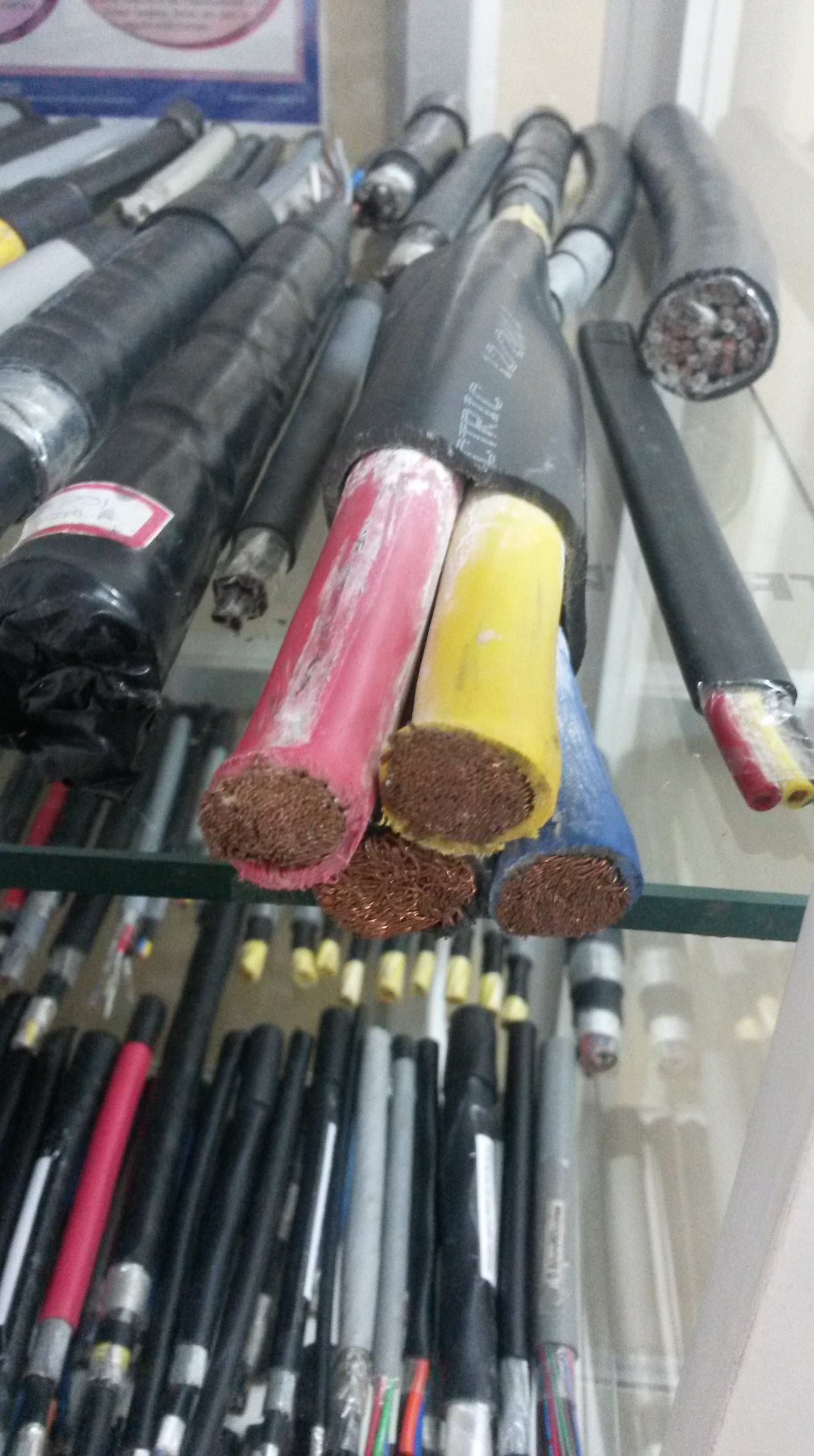
Sometimes, for cables carrying extremely large currents, there can be many layers of insulation as the cross section of the wire shown below illustrates.
Step 6: Final Extrusion:
After the desired number of insulating layers is applied, the wire undergoes final extrusion, where a thicker layer of PVC coats the smaller, insulated wires. This step is only required for cables carrying large currents.
As shown, the bundled wires (on the right of the picture) are covered in chalk powder to ensure the thick layer of PVC extrudes the wire effectively.
Step 7: Packaging:
The insulated wire is finally wound, and is ready for transportation.

Injection Molding
BlogStep 1: The Raw Material
Plastics are organic compounds that are derived from a mixture of petrochemicals. Made up of mainly carbon, sometimes along with oxygen, nitrogen or sulfur, the chemical composition of plastics are essentially organic polymers, i.e., a substance which has a molecular structure built up chiefly or completely from a large number of similar organic units bonded together.
The plastic is bought in the form of granules, as shown in the image below. The granules can be bought in different colors, depending on the requirements. Granules are a convenient form as they expose a larger surface area of the plastic, which reduces the amount of heat energy that needs to be applied to melt the plastic in Step 2.

Step 2: Melting and Pumping
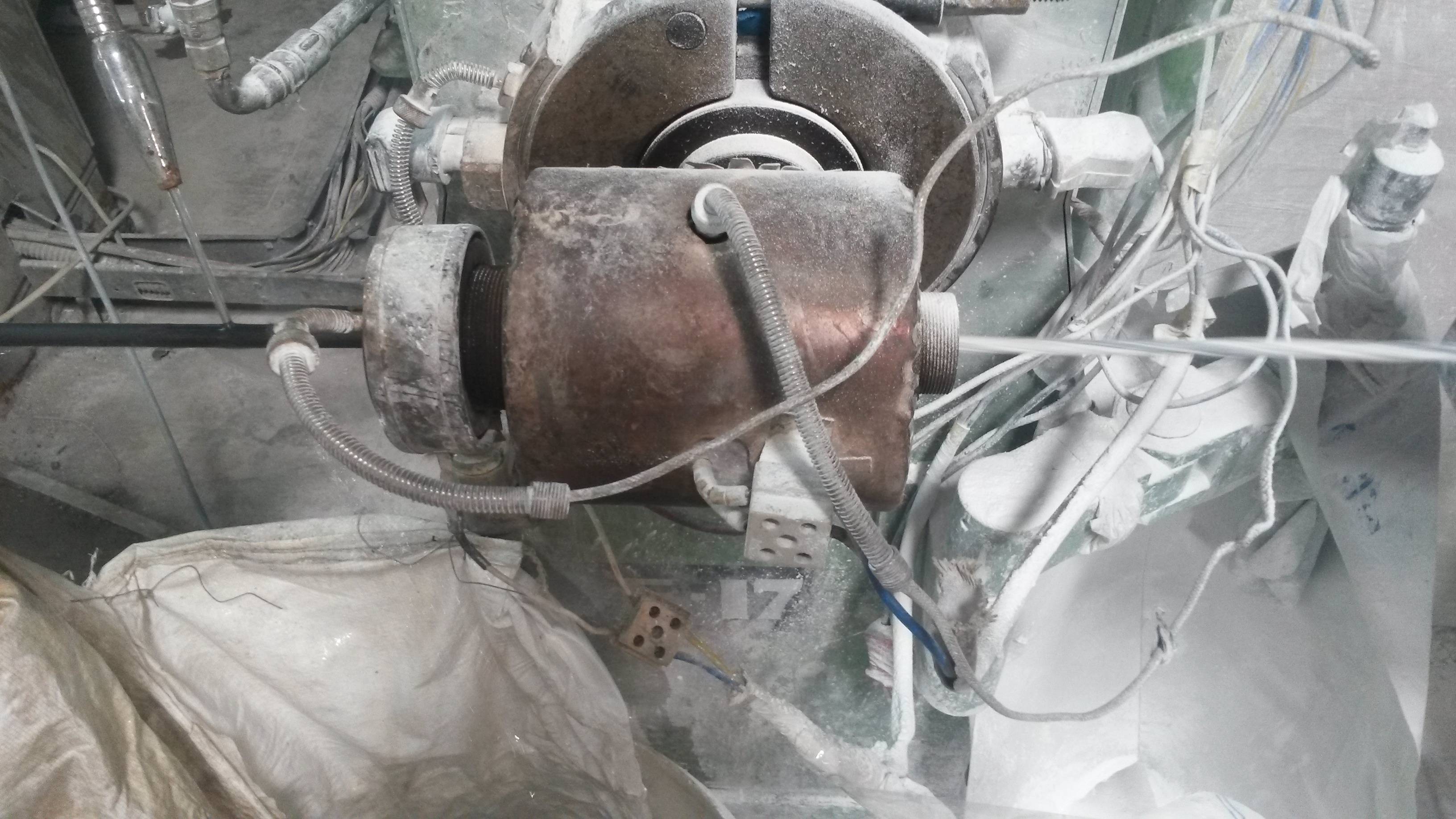
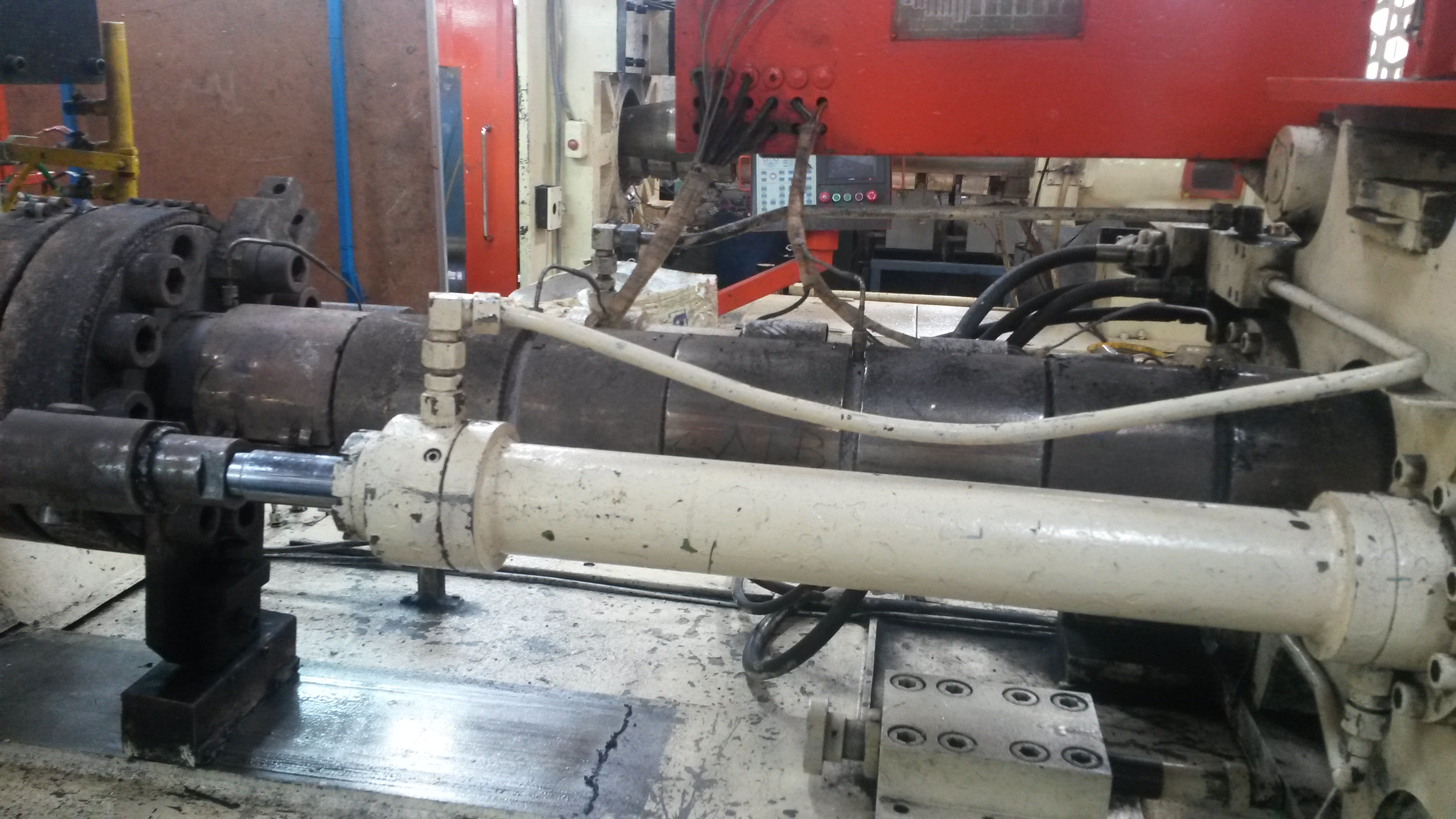
The plastic granules are heated to approximately 700 degrees Celsius and then pumped through the pipes shown below.
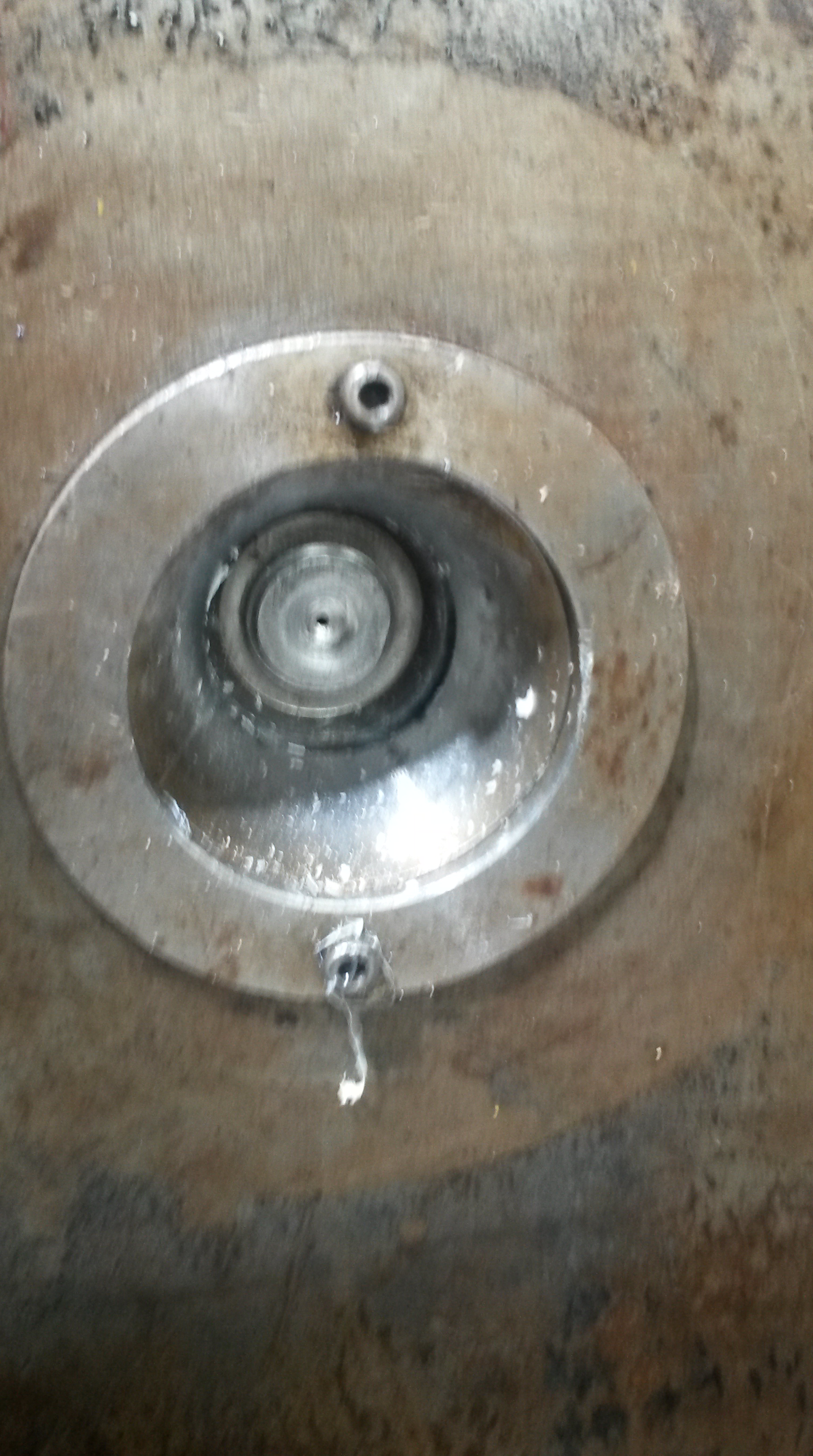
At the end of the pipe, there is a small opening through which the plastic flows out and enters the mould as the figure below illustrates. The size of the opening is extremely small to ensure an even flow of the plastic. The speed of flow also needs to be controlled to ensure that the right amount of plastic flows through the hole.
Step 3: Moulding
The actual mould has two parts – a cavity and an insertion. Both are made out of metal, as metals have high melting points and can withstand the high temperature of the plastic that flows into the mould. The cavity and insertion are shown below; the insertion leaves a gap in the cavity which is filled by the plastic. The insertion also has intricate carvings, inside which plastic also flows.

The injection mould is designed in such a way that it mimics the final gaps in the plastic that the product requires.
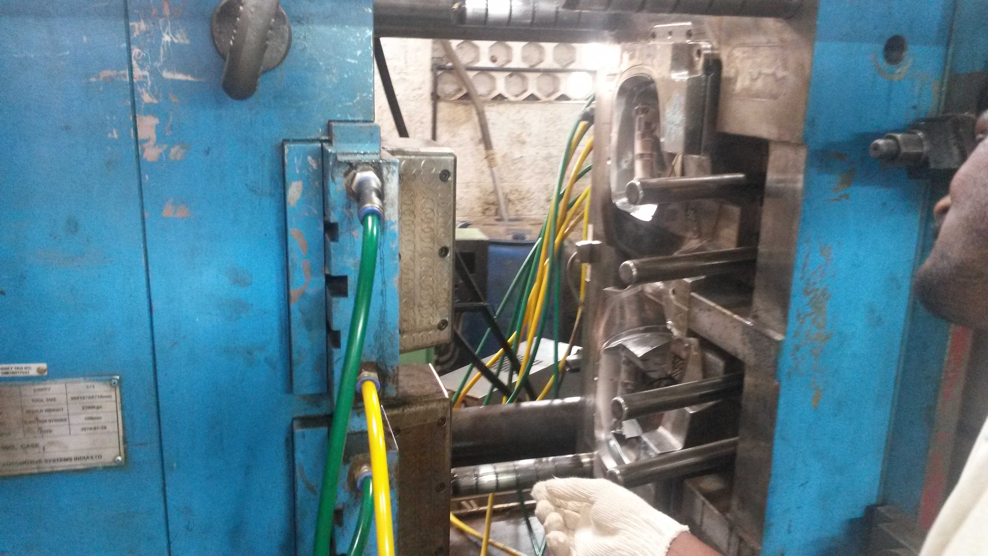
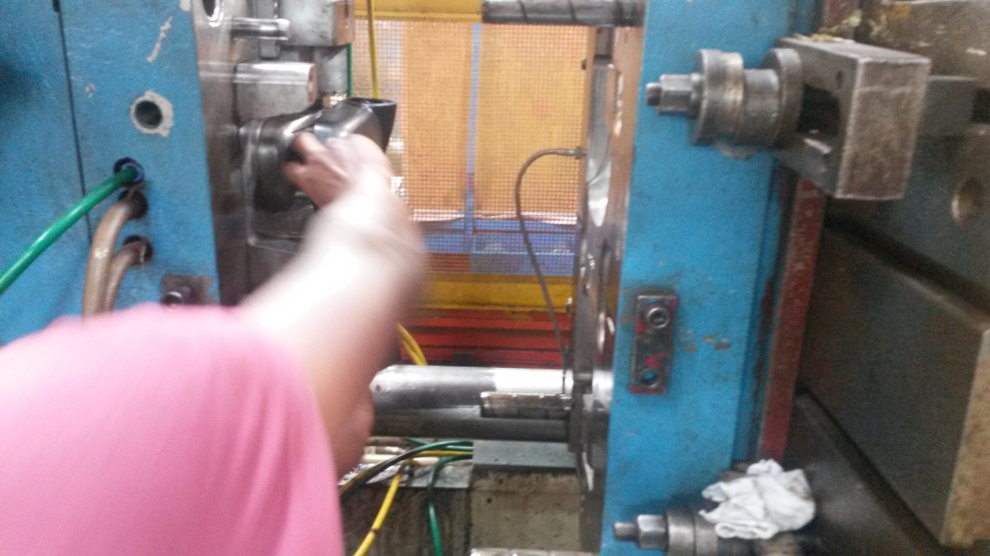
The two parts of the injection mould are then pushed together, as shown. This triggers a valve to open allowing the molten plastic to flow into the mould. The machine is timed so that it closes for the length of time that is required for the molten plastic to flow into and completely fill the mould. Simultaneously, the yellow and green pipes shown bring in water and take out water that cool the molten plastic, solidifying it.
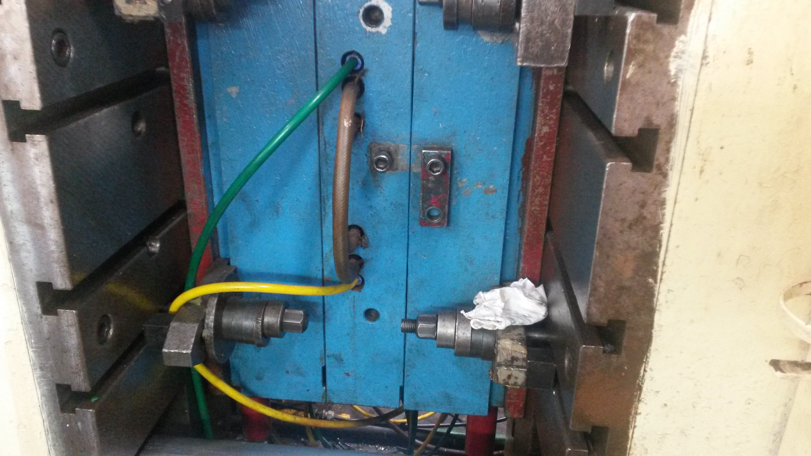
After the required amount of time for the molten plastic to fill the mould and then cool, the cavity and insertion parts of the mould separate once again and the moulded solid plastic is manually removed.
Step 4: Cooling
Although the cooling system in-built in the mould solidifies the molten plastic, sometimes additional cooling is required. This is either done by immersing the product into water or by just letting them rest, in which case they are cooled by the atmosphere.
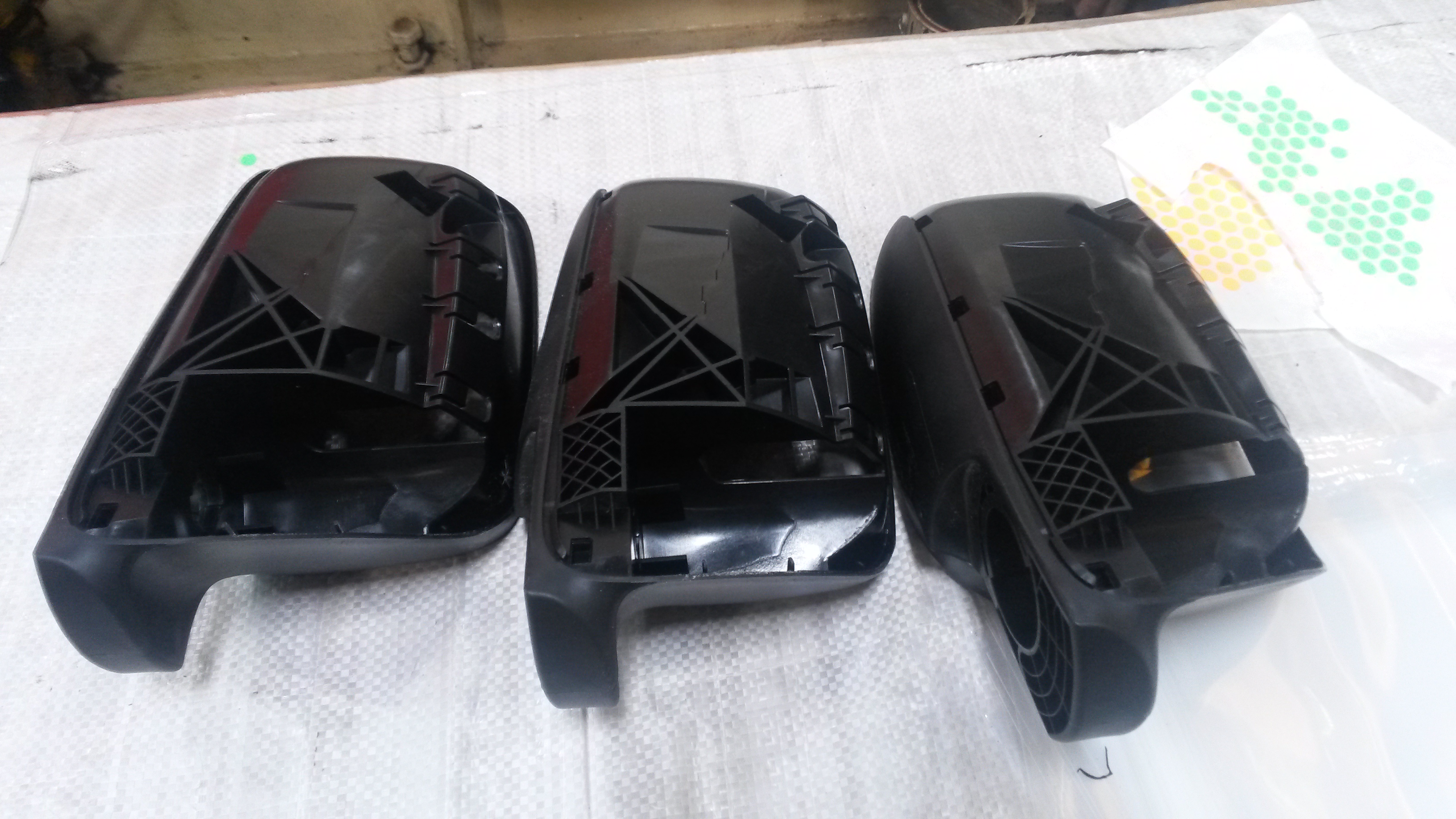
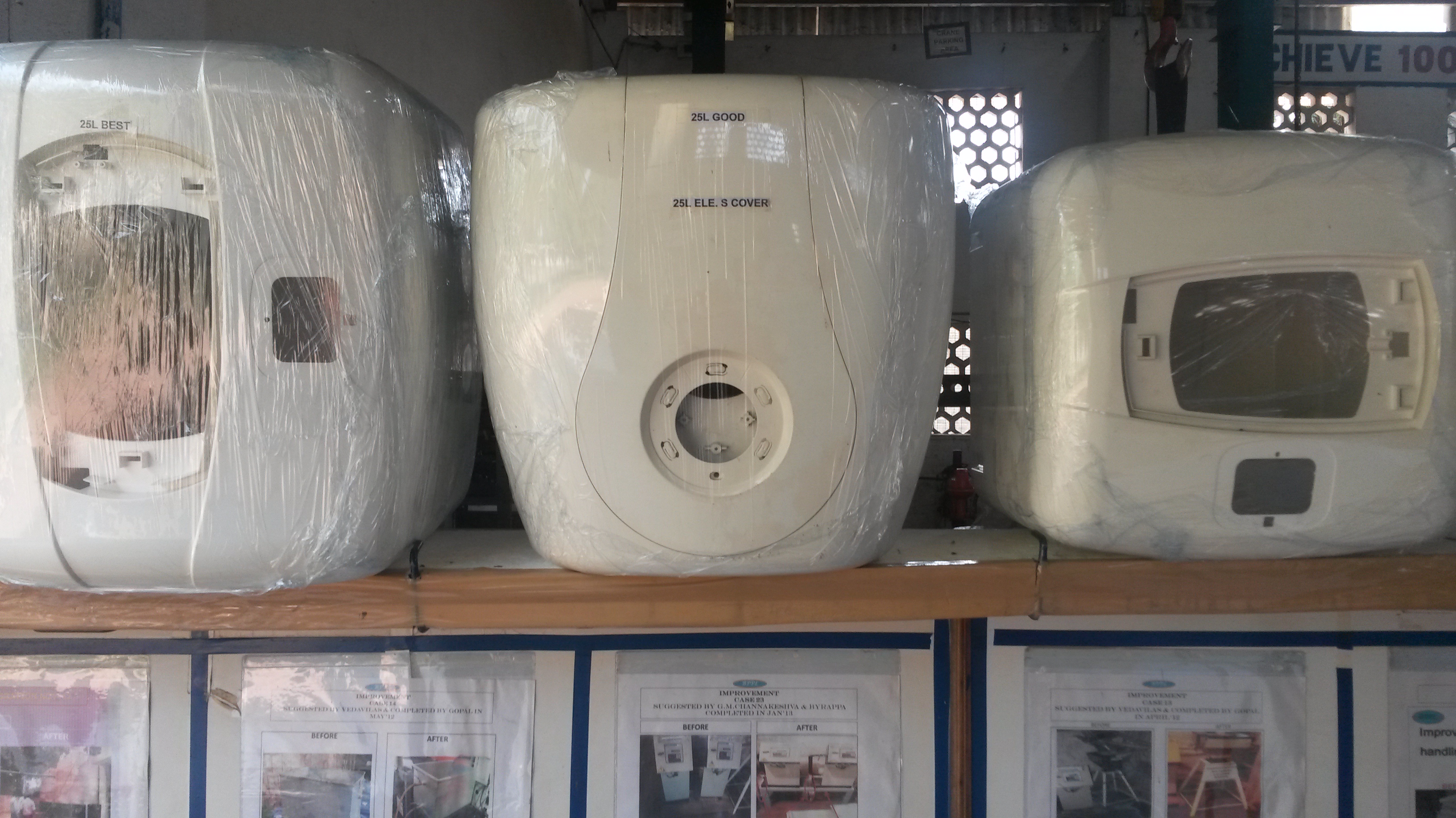
The Finished Product:
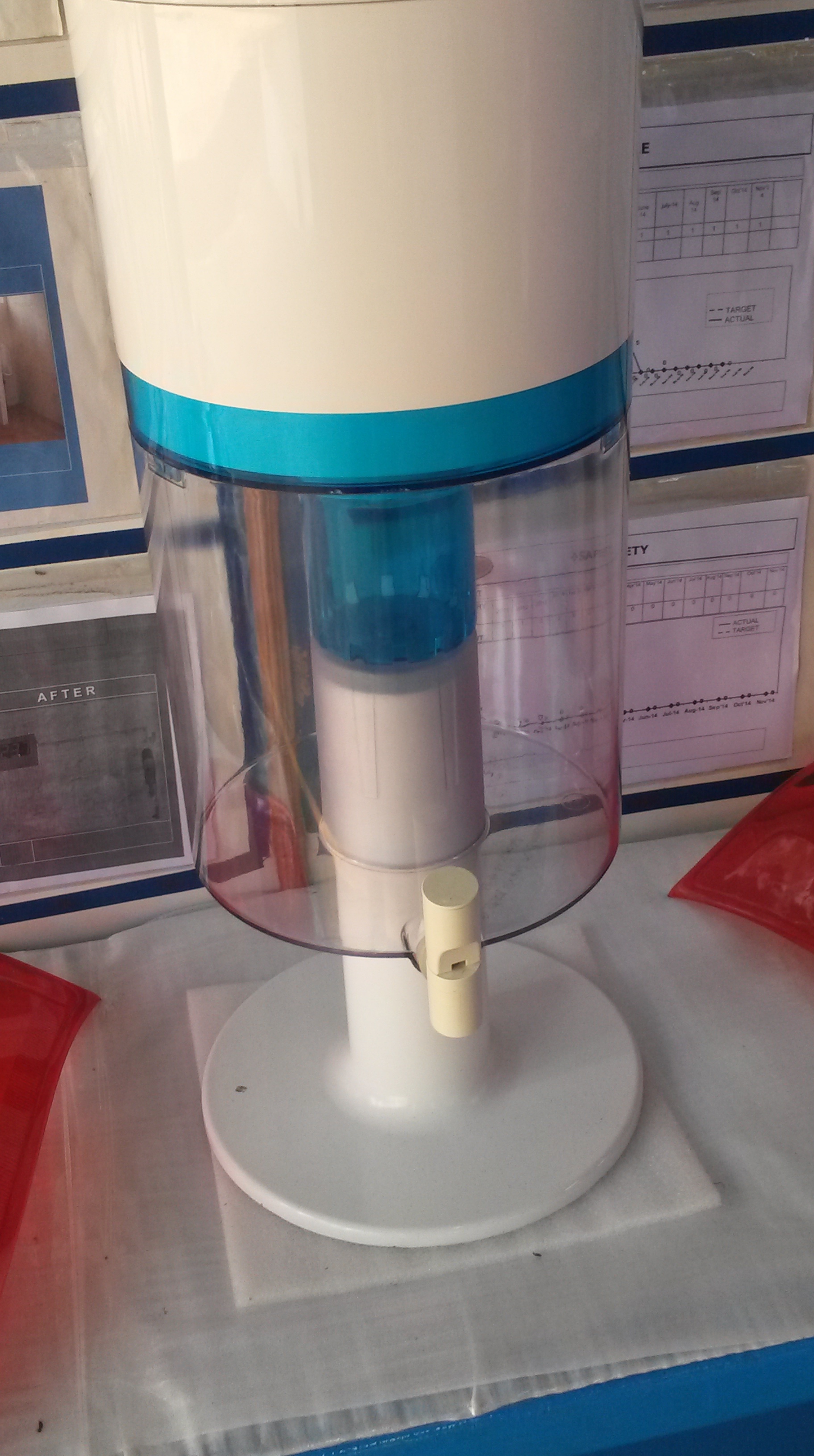
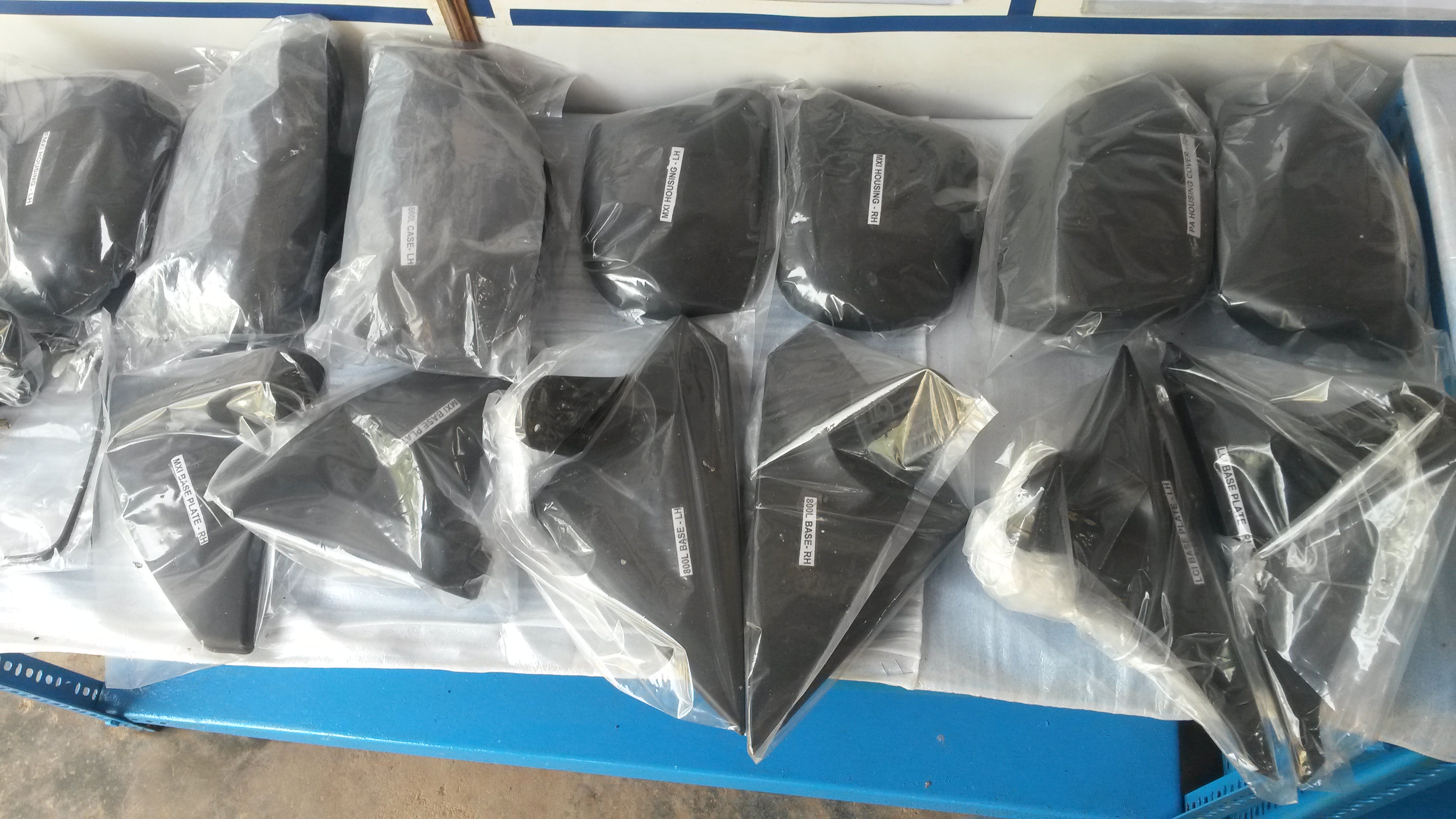
After cooling, the product is packaged and prepared for delivery to the various industries in which they are used. Some of the products made in the factory I visited are side- view mirror holders, the body of water heaters and the body of water filters, as shown below.
Paper Plates
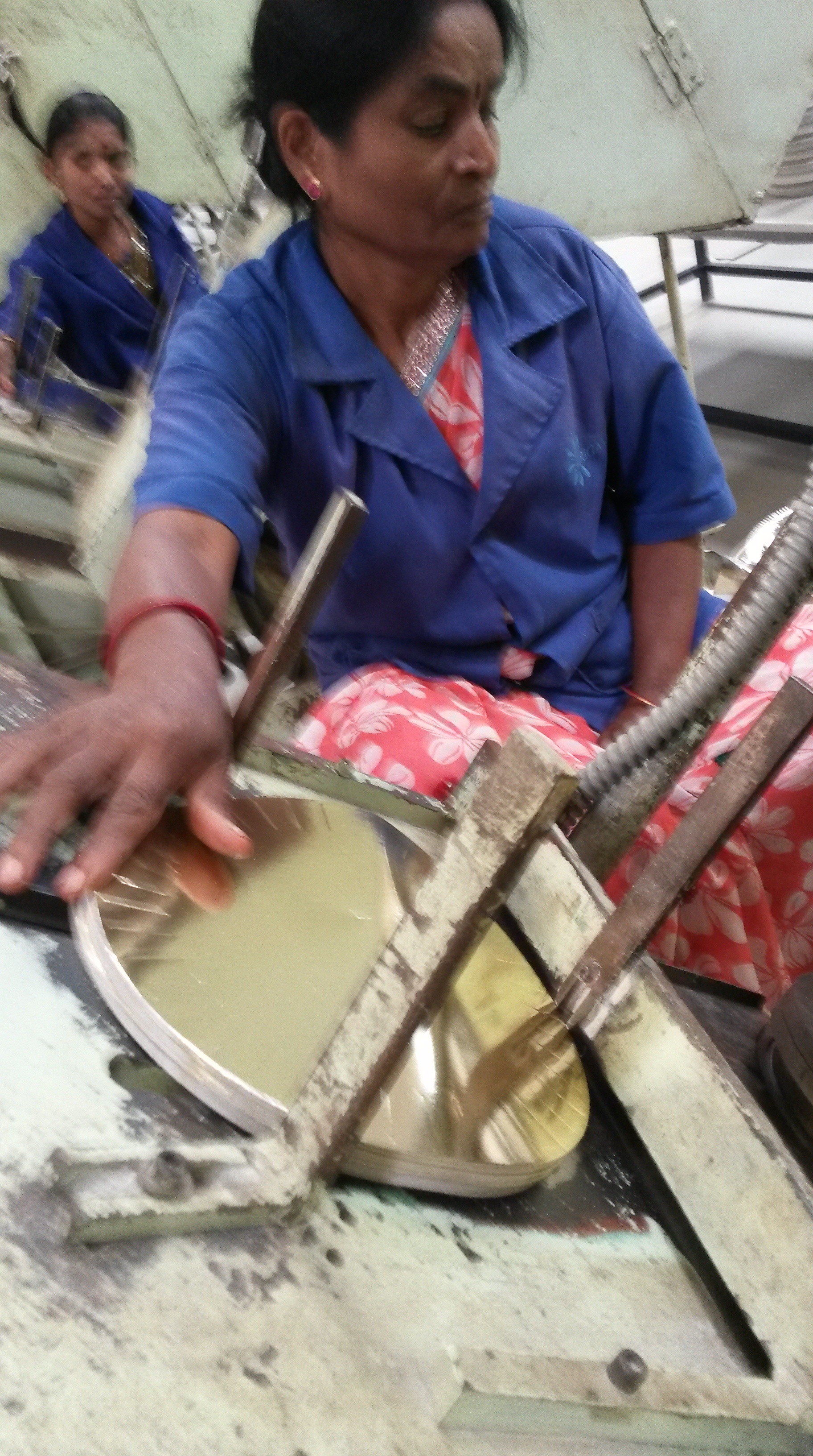
Blog- Similar to the process of paper cups, paper plates also start out as a piece of cardboard. The cardboard is then put into the machine shown below. The two ends of the machine converge and engrave the shape of the plate onto the cardboard. The force that the two ends of the machine exert squishes the sheet of cardboard onto the engravings. Due to the force the cardboard fits into the small depressions on the metal plate, engraving the shape of the paper plate onto the cardboard

The circles engraved are then cut and fed into the machine.

2. Using the principle of suction the pieces of cardboard are fed into the machine one at a time.
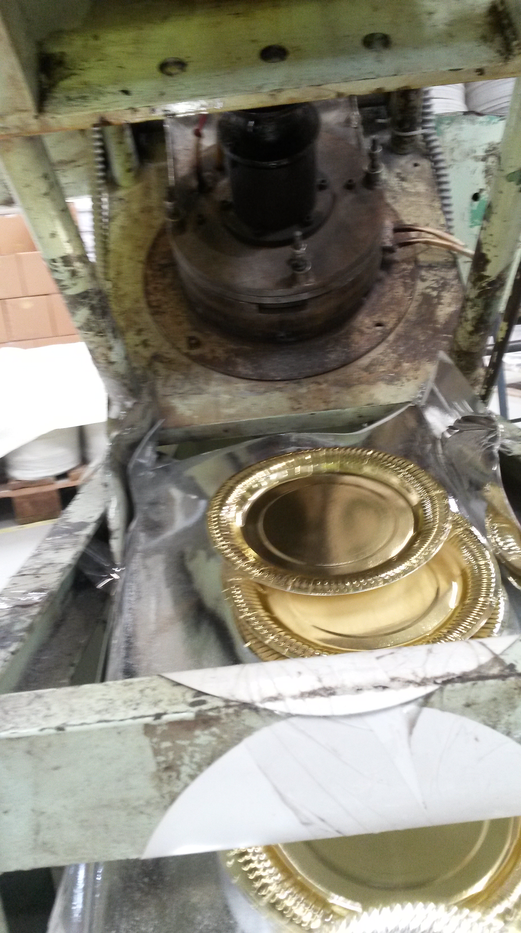
3. The machine is timed in such a way that as soon as the cardboard piece goes into the mould a rod from above moves downward. At the end of the rod, a metal piece is attached that fits perfectly into the mould below. The metal piece from above is also heated which makes it easier for the cardboard to be moulded into a plate.

The timing of the rod moving downward is not controlled by sensors, but is controlled mechanically. The rod which moves the cardboard down in step (b), triggers the movement of the rod moving downward onto the paper plate mould. Sensors could also be used, but the mechanical method is cheaper, thus is used.
The rod then moves upward again to reveal that circular piece of cardboard that is now a paper plate. The plate slides downward and another circular piece takes its place in the mould before the rod comes down again.
4. The plates are then manually counted and wrapped in shrink wrap before being sealed with a hand sealing machine. The machine applies heat onto the shrink wrap and melts it. Thus, the shrink wrap gets cut off and wraps the plate, as the picture shows.
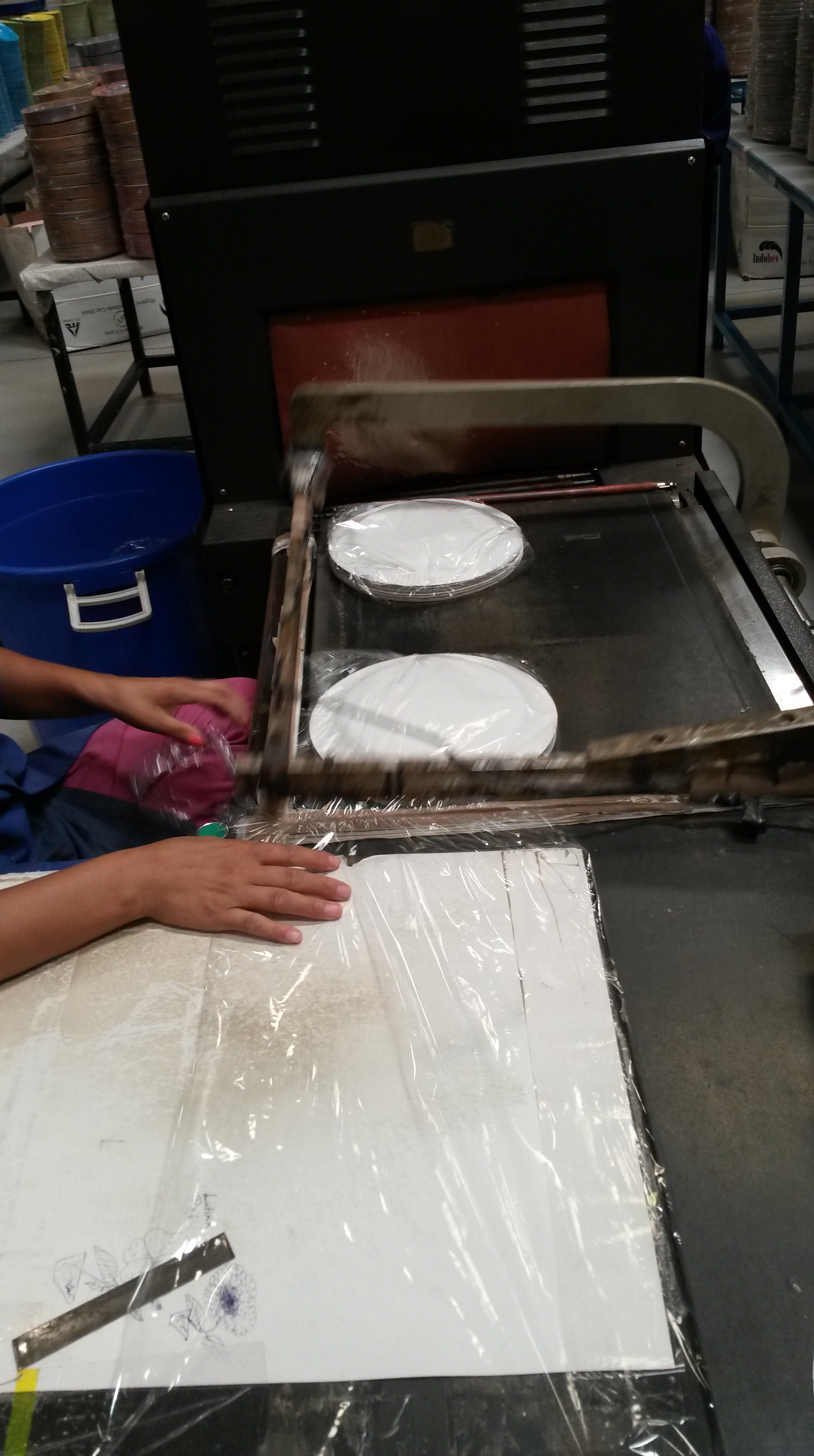
However, the shrink wrap is still loosely packed around the plates. To solve this problem it is put onto a conveyer belt which flows through a heated chamber. Normally, materials expand on the application of heat. However, shrink wrap shrinks, thereby allowing the plastic to firmly wrap around the stack of plates.
So how does shrink wrap work? Shrink wrap is made out of polymers (a long chain of small molecules that combine to form a macromolecule) that are oriented in an elongated state, as shown below. However, on the application of heat, the polymers break out of this elongated state and become entangled. As a result, the shrink wrap shrinks and firmly wraps around the plates.
Paper Cups
BlogAs part of my visit to a paper product making factory, I documented how the paper cup making machine works. Enjoy reading!
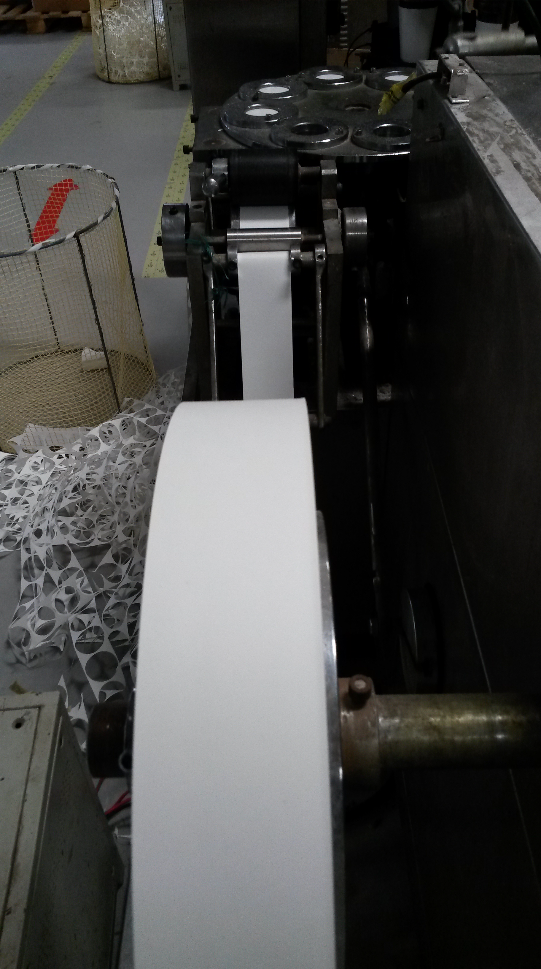
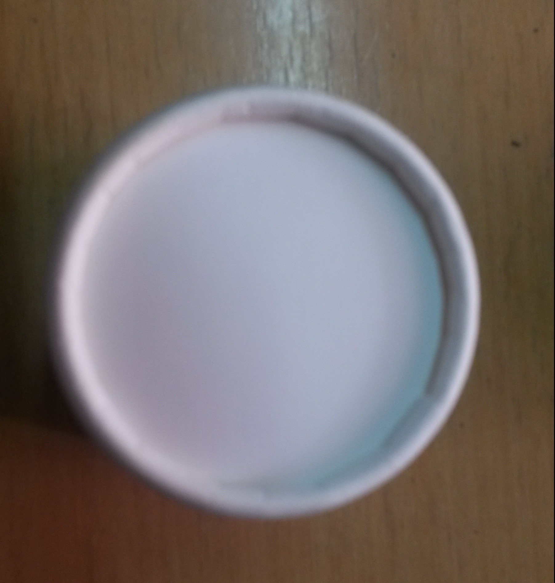
Step 1: The Raw Material
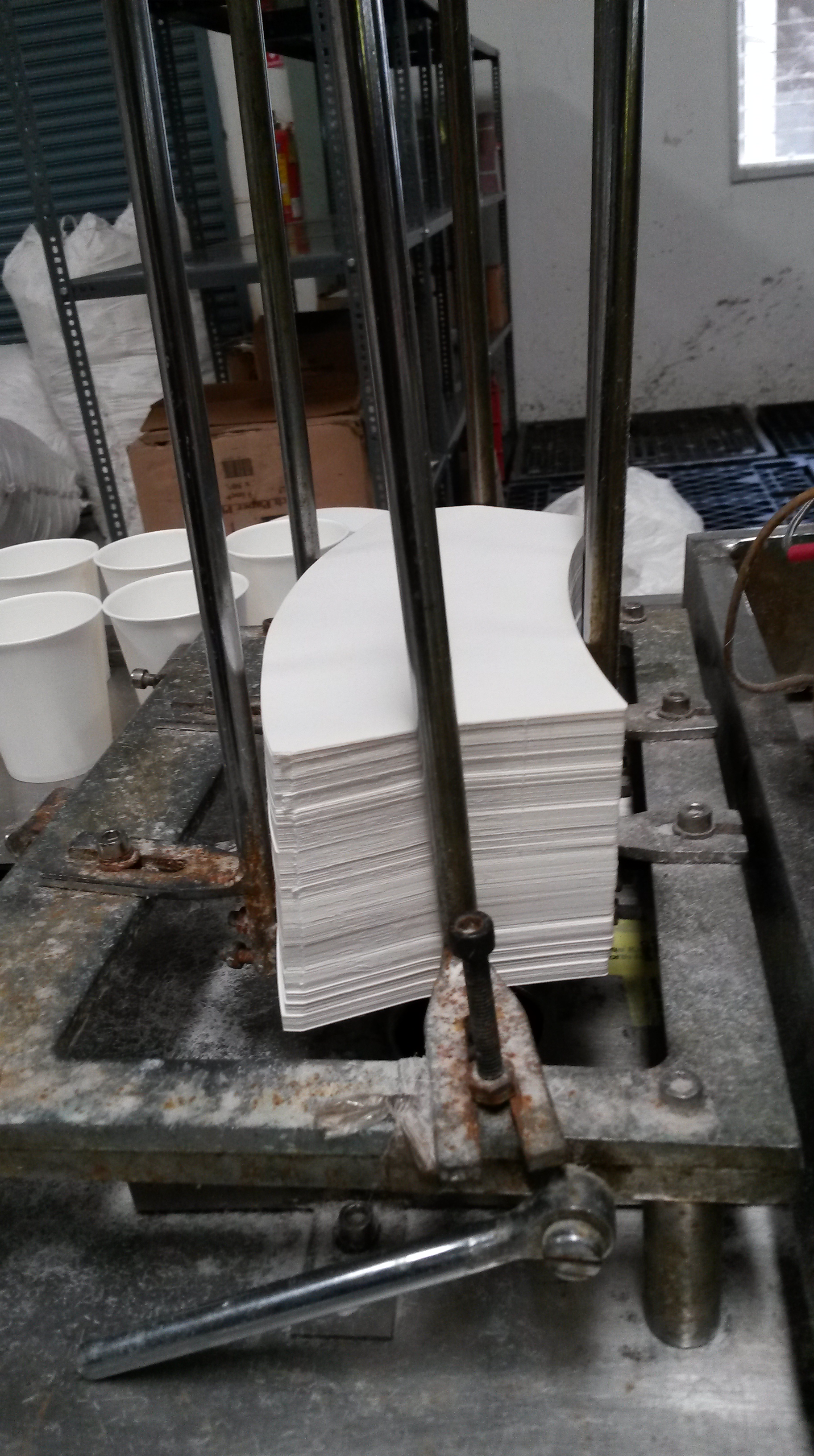
The first step in the process of making paper cups in the factory is to cut cardboard into pieces of the shape shown below. To ensure the final paper cup has a smaller base than rim, the initial cardboard shape is not a rectangle, but of the shape shown below:
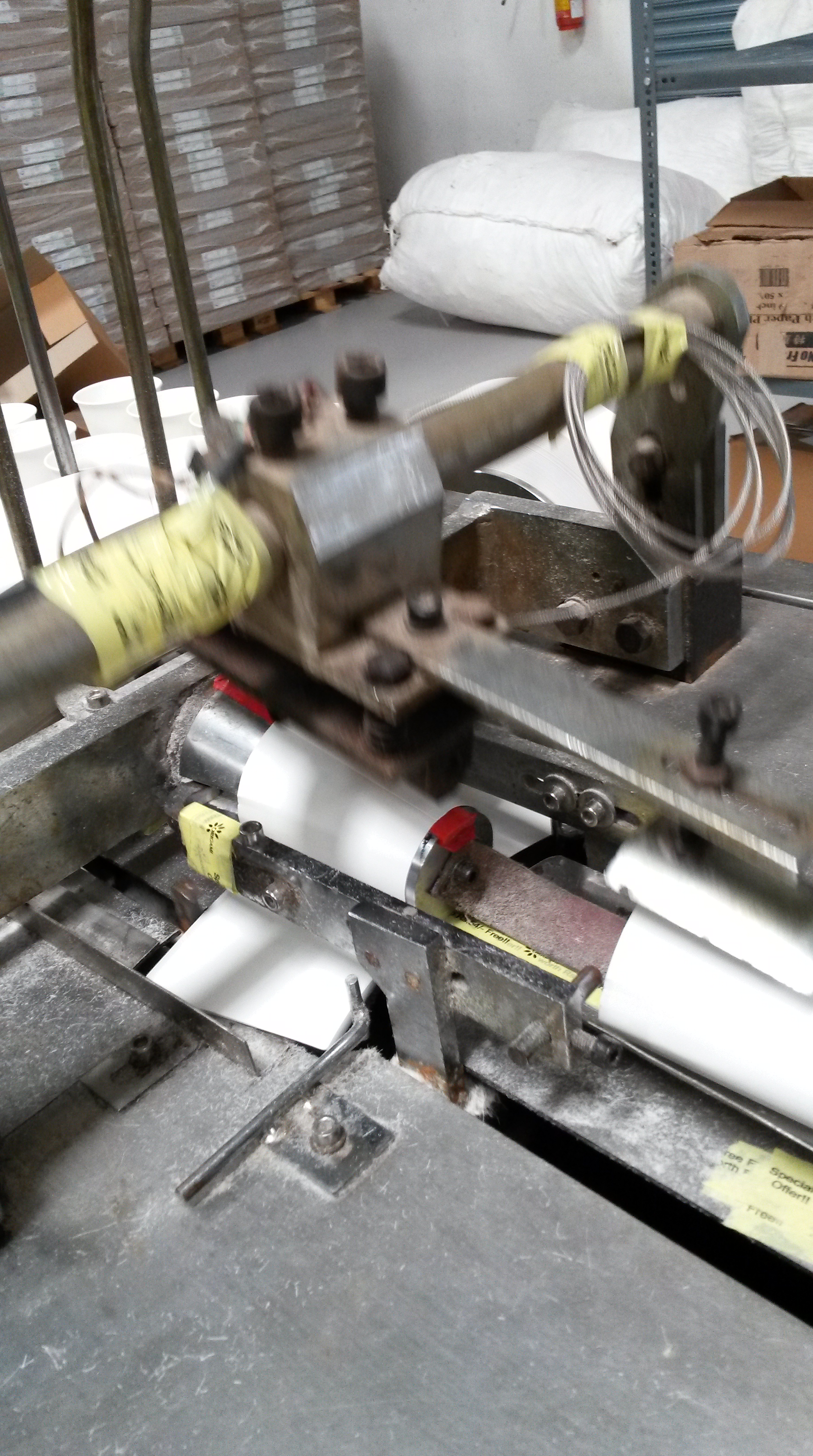
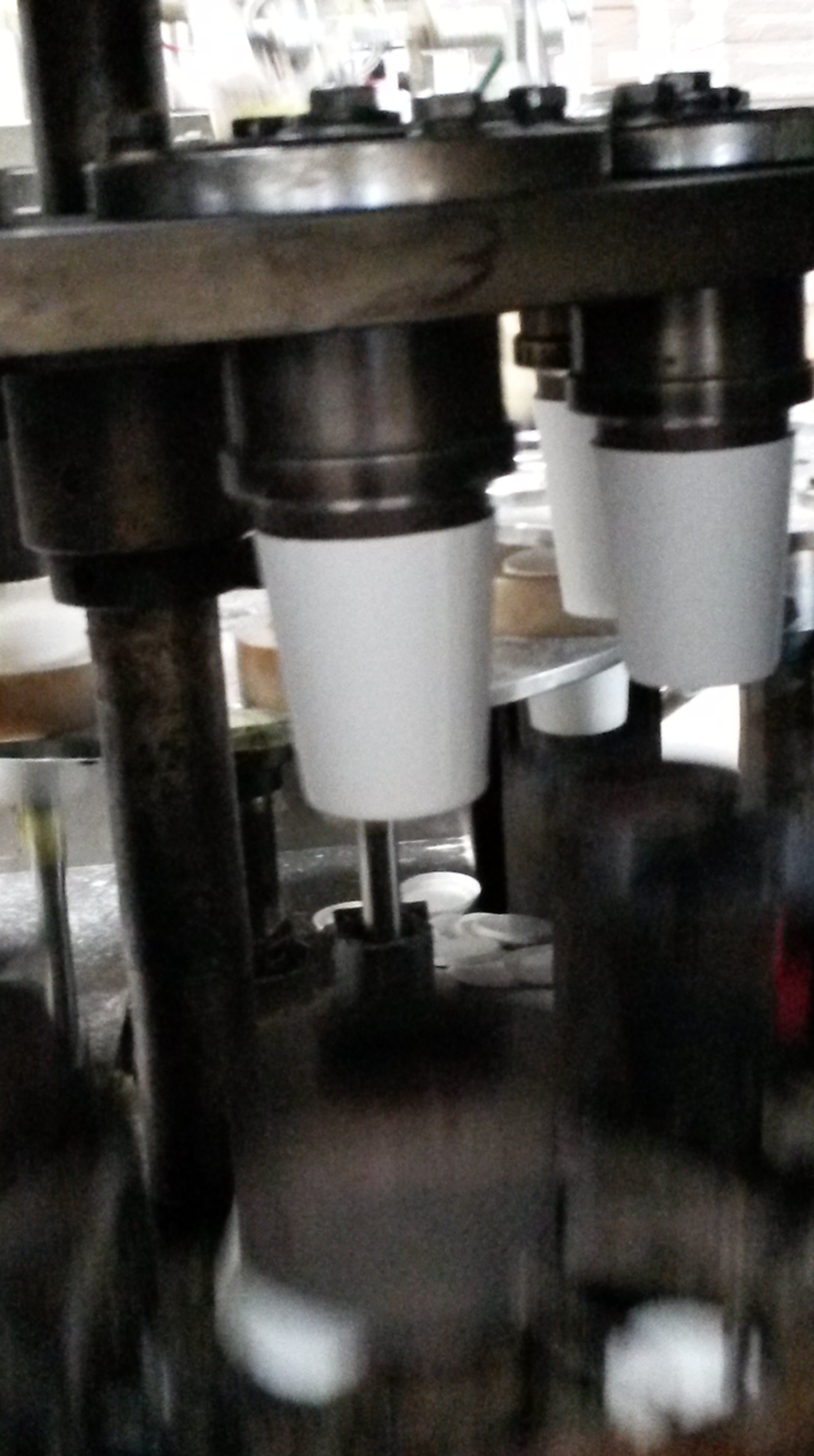
Step 2: Forming the basic shape of the cup
The pieces of paper are stacked one on top of the other and one by one taken into the machine. To ensure that only one piece goes into the machine at a time, there is a tube at the bottom of the stack. The pressure in the tube is controlled so that it is less than that of atmospheric pressure. The pressure differential between the tube and the air surrounding the paper creates a force, which draws the paper towards the tube. The same principle is used in vacuum cleaners and the effect is referred to as suction. However the difference between the two is that the air pressure inside the tube is only a small fraction lower than that of atmospheric pressure. This small pressure difference is just enough to ensure that only the bottom piece is taken and dragged towards the machine.
This piece then is grabbed on either side by two jaws that then bend to curve the piece of cardboard around a metal mould of the cup. From above, a heated piece of machinery comes downward and presses itself onto the curved cardboard. Due to the heat applied the paper partially melts and the liquid produced acts as a glue to seal the paper while it is in the shape of a cup. The temperature must be maintained so that it is high enough so that the paper only partially melts, but not too high to ensure it doesn’t completely become liquid.
 The rounded and sealed paper then drops into a circular ring that rotates.
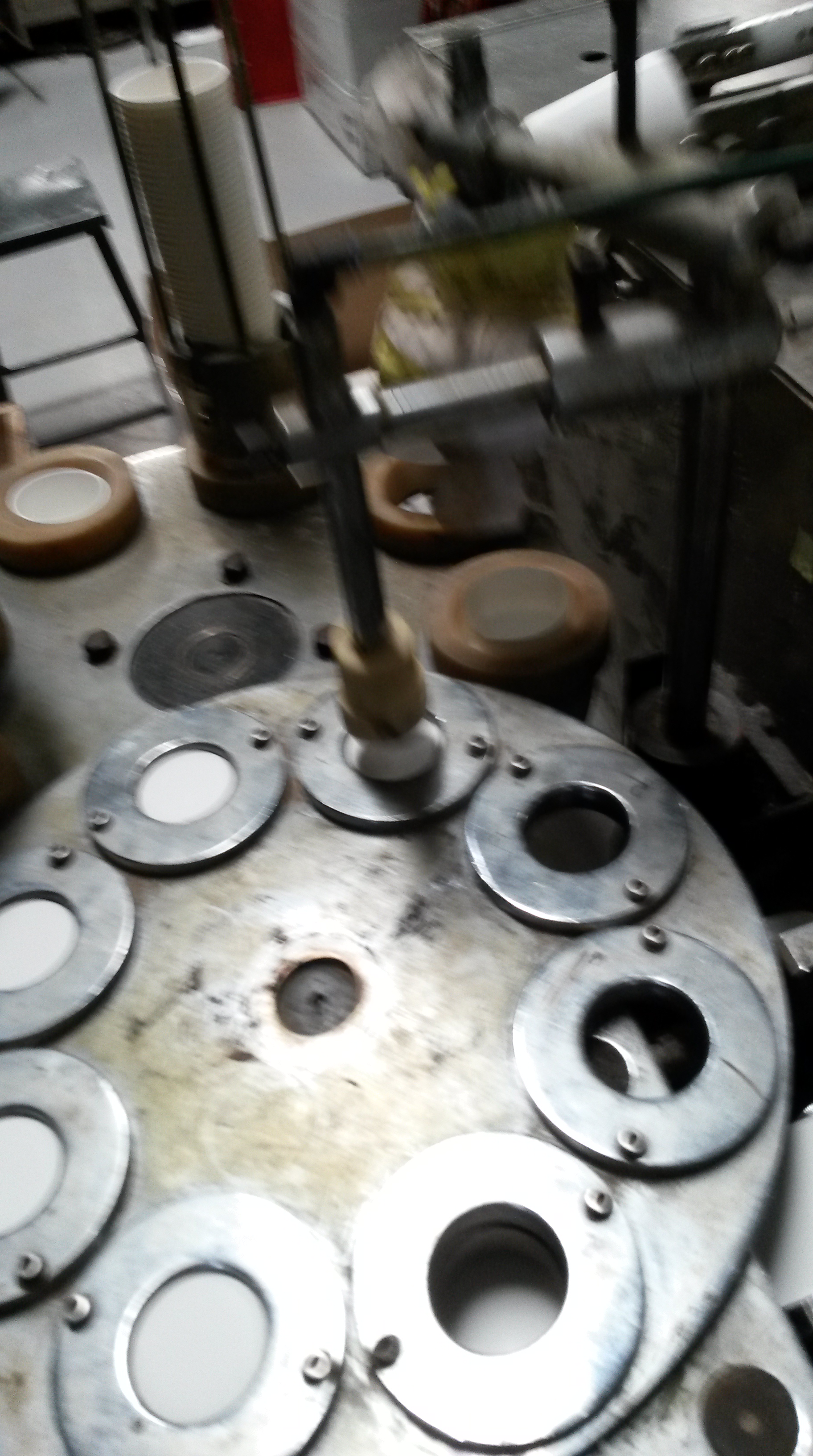
Step 3: Temporarily attaching the base:
Simultaneously a thin roll of cardboard is fed into the machine and circular pieces are cut by a mould, which eventually form the base of the cup. The circumference of these circular pieces are equal to the length of the bottom curved section of the piece of cardboard in stage one. This ensures that the base fits perfectly into the cup.
These small circular pieces of paper go into another circular ring that is identical to the one the rounded and sealed paper goes into in stage (b), but is at a higher level. The two circular rings rotate at a specific rate to not only ensure that the rounded, sealed paper/ circular pieces proceed into the hole, but also so that the holes of the two rings intersect. When they do intersect, a vertical rod from above moves downwards and pushes the cut circular piece of paper into the bottom of the rounded, sealed paper, forming a base. The circular paper simply doesn’t fall through as its circumference is equal to the bottom of the rounded paper. Therefore, it rubs against the sides of the rounded cardboard, creating friction which opposes the downward motion, eventually making it stop or get stuck, to form the base. The force with which the rod comes down should also be regulated so that the downward force is enough to make the paper stop at the base, but not too much to make the paper fall through.
However, the base is only temporarily attached and would fall through if anything was stored in it. Therefore, the paper cup is not ready yet.
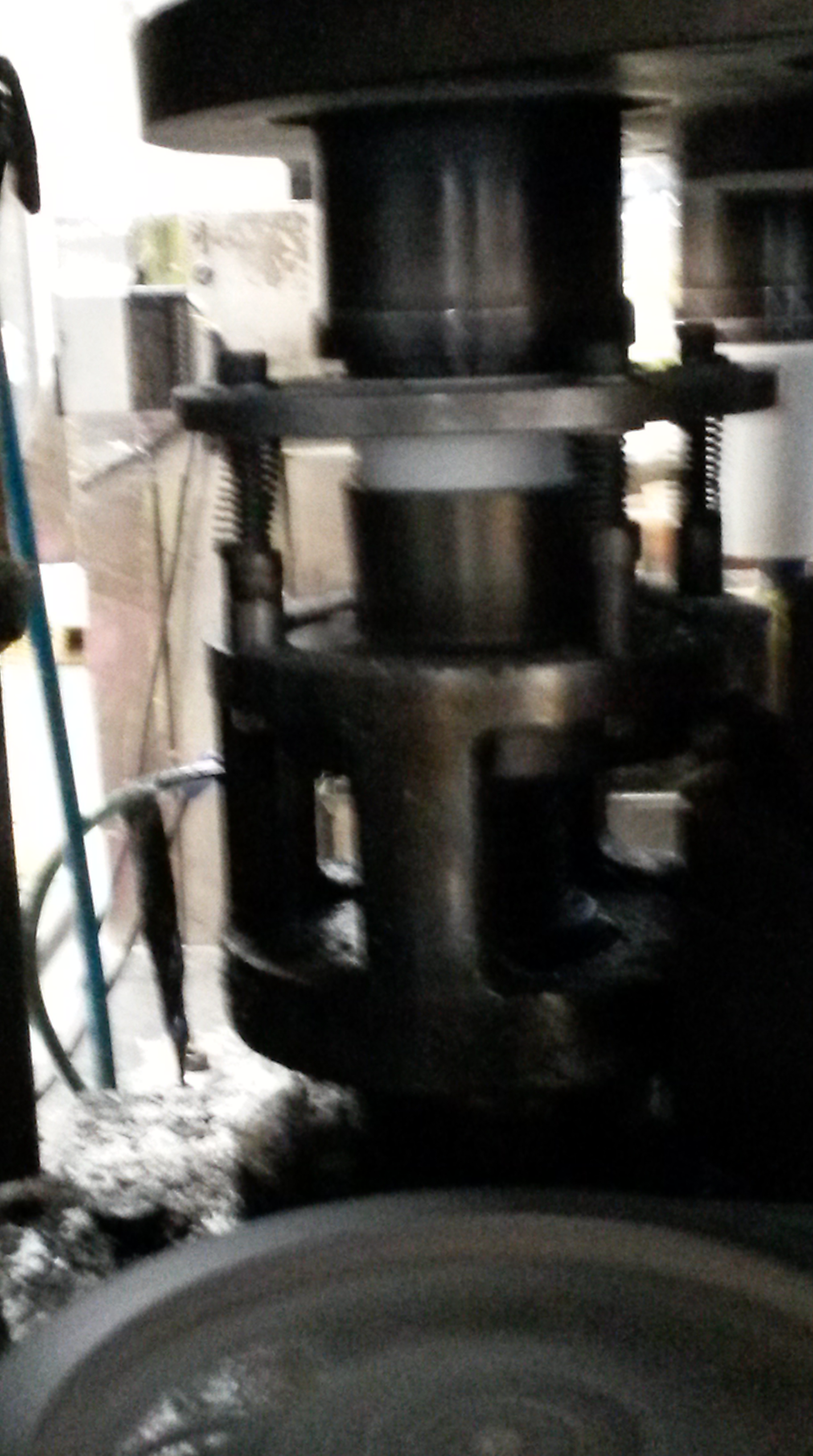
Step 4: Permanently attaching the base:
To make the base stronger and more permanently fixed, the same heating effect is used to seal the base to the cup as in stage (2).
The rounded piece of paper with the base temporarily attached is pushed upward onto a steel mould of the cup. Immediately, a heated rod with a circular end (the same size as the base of the cup) is pushed upward and pressed onto the bottom of the cup. It pushes the base slightly upward before bending the rounded piece of cardboard upward. Due to the heat, the base and the rounded cardboard are stuck.
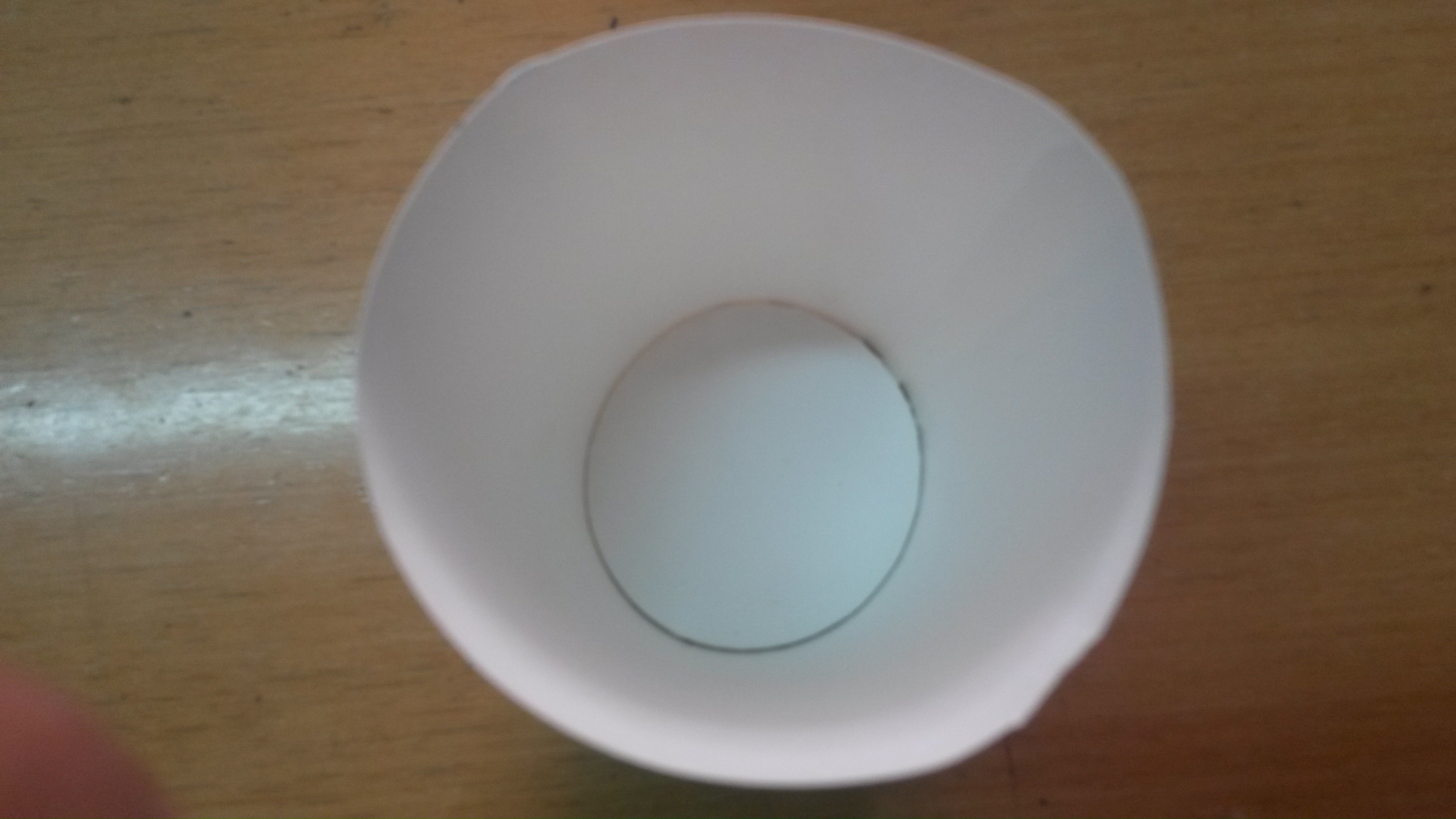
The result of this process is a cup that can be used. However, one final step of the process remains.
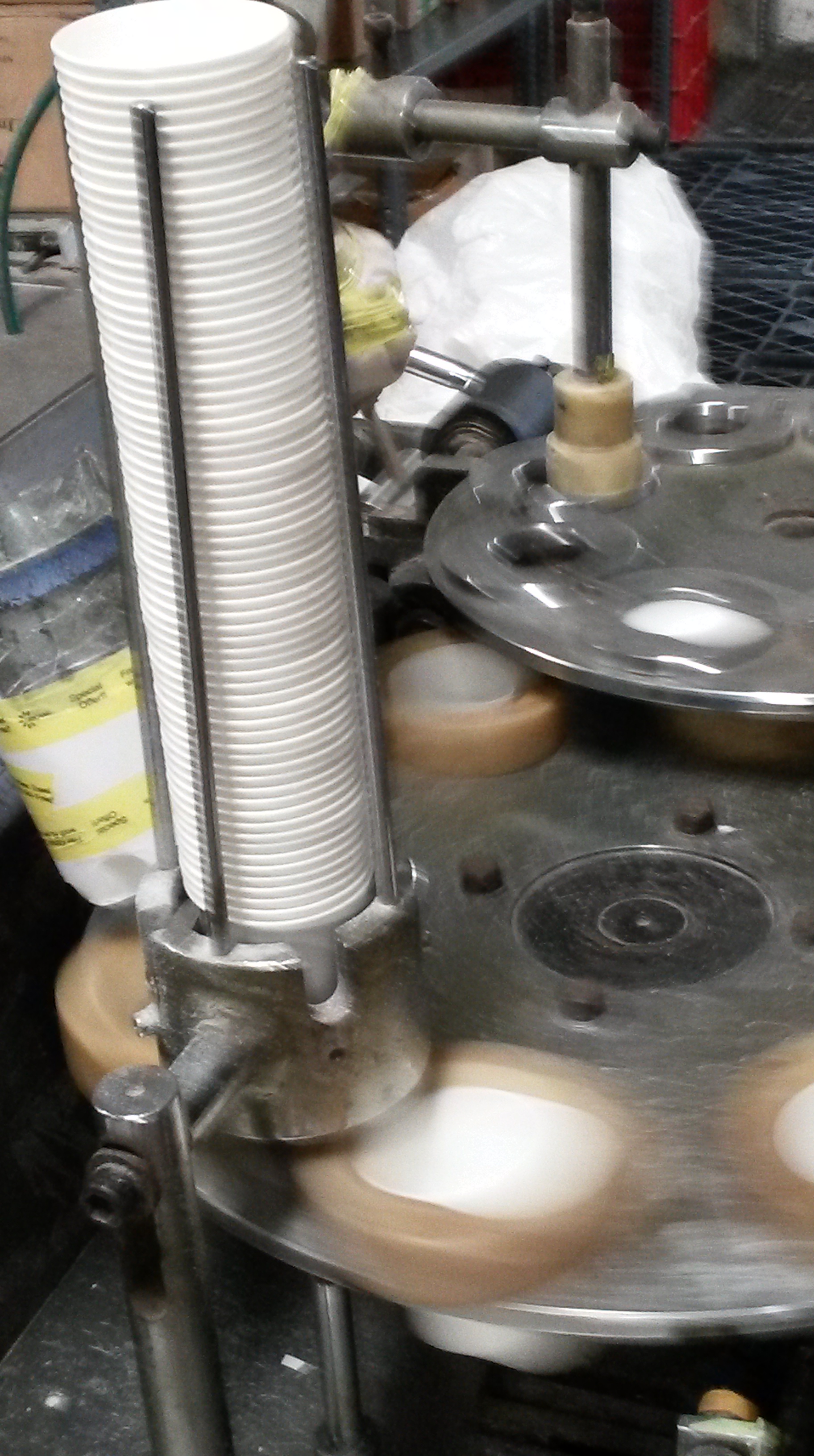
Step 5: Rounding the top of the cup:
As you may have noticed, the top of paper cups are rounded. This not only makes it easier for drinking, but also makes the cup more rigid and stable. The same heating effect is used to curl the cups and then keep them in position, as shown below:
Finally, the paper cups get stacked one on top of the other in a collector, ready to be packed and sent into the market.
Paper Napkins
BlogHere’s a look at how a paper napkin machine works!
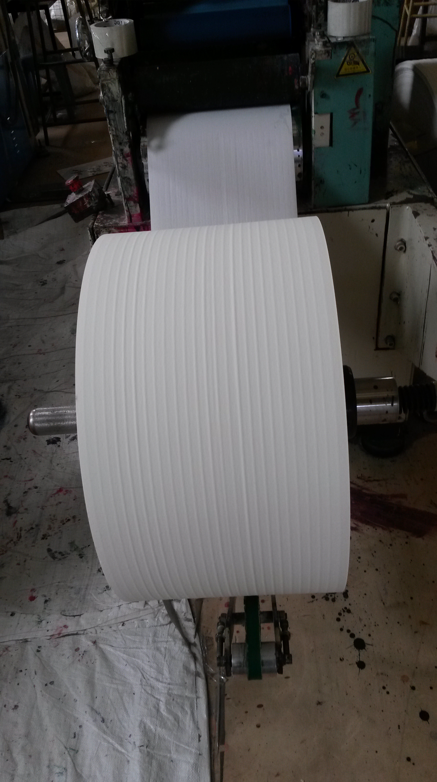
Step 1. Raw Material Insertion:
First, a roll of tissue paper is fed into the machine, as shown in the photograph below.
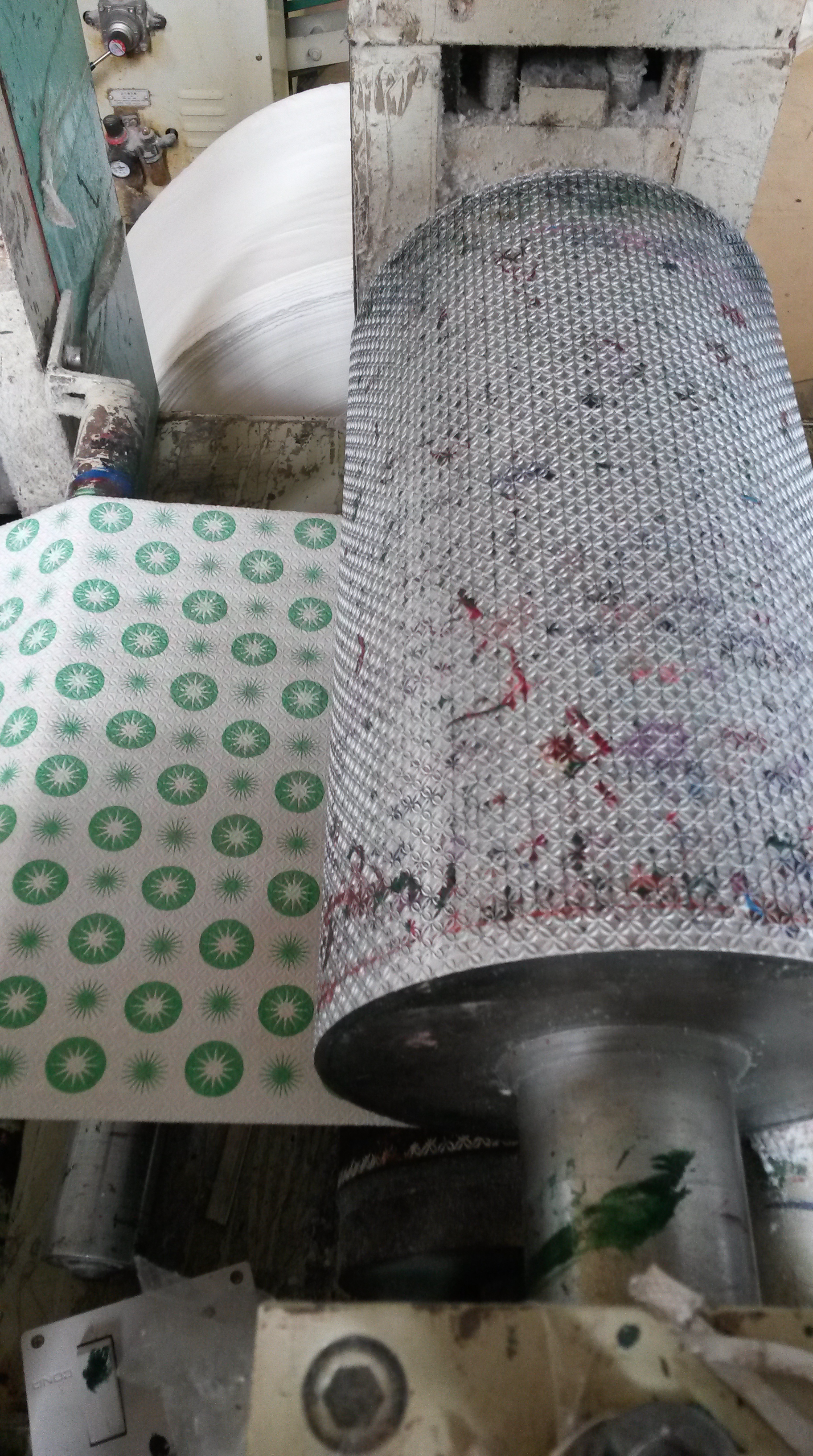
Step 2- Printing:
Three rollers are placed over a container of ink. The first roller rotates so that it gets covered in ink. Simultaneously, the other rollers (which are in contact with each other) also rotate. Thus, the first roller transfers the ink that it has picked up to the second roller. The second roller then rubs against the third one. The third roller, as you can see has rubber pieces stuck on it in a particular pattern, i.e. , the pattern that needs to be printed. The rubber pieces absorb the ink from the second roller. The first roller does not directly transfer the ink to the third one, as it picks up too much ink. However, only a fraction of that ink (the amount that is needed) gets transferred to the second roller, which in turn is absorbed by the rubber pieces on the third. Any ink that is not absorbed by the roller/ rubber pieces in returned to the container, ensuring minimum wastage of ink, making the process efficient.

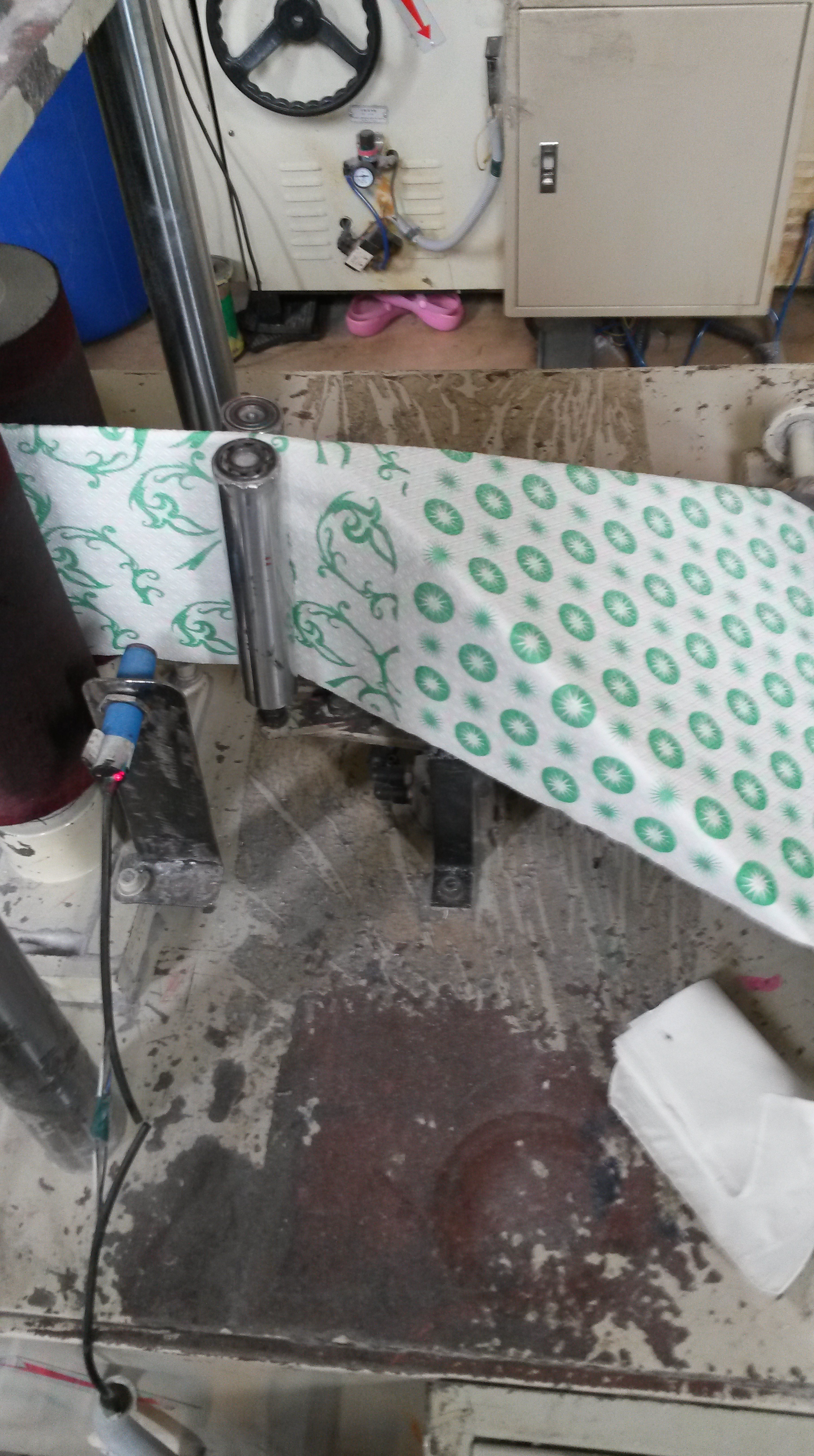
The paper moves forward and winds over the third roller. Like a rubber stamp, the rubber pieces of the roller transfer the ink to the paper in the particular design. The speed of the roller must be regulated so that it is not too slow (which would result in too much ink on the paper) or too fast (which would result in too less ink on the paper)

Interestingly the machine has the capability to print two different designs at the same time. This is achieved as half of the third roller has rubber pieces of one design, while the other half has rubber pieces of the other design. The surface area of the roller is equal of the surface area of exactly two napkins. Therefore, two napkins with two different designs can be printed easily.
Step 3- Embossing:
The printed paper then gets embossed, i.e., gets pressed against a roller so that there are small raised portions and depressions of the paper. The roller shown in the photograph below has an extremely uneven surface with regular, small depressions. Once the paper rubs against this roller it fills in these gaps in the roller, which result in the paper also having an uneven surface.
Why do this? Well, the embossing in the paper gives it a fluffiness. When the napkins are stacked one on top of another, the embossing means that there would be air gaps in between the napkins. Thus, this makes the tissue look more fluffy, which would attract consumers to buy these napkins.
Step 4- Folding and Counting:
The printed and embossed paper is then folded, as shown below. The machine contains a triangular metal plate that is placed at an angle. The paper goes over this plate, thus is rises. Two rods are placed right after this triangular plate. The paper that goes over the top edge of the triangular plate proceeds into the rods. The rods rotate, which results in the rest of the paper also following, thereby getting folded.
The small blue device in the picture is a counter. After it senses that a particular length of paper has passed it the count increases by one. The machine, therefore, also counts the number of napkins it makes.
Step 5- Cutting:
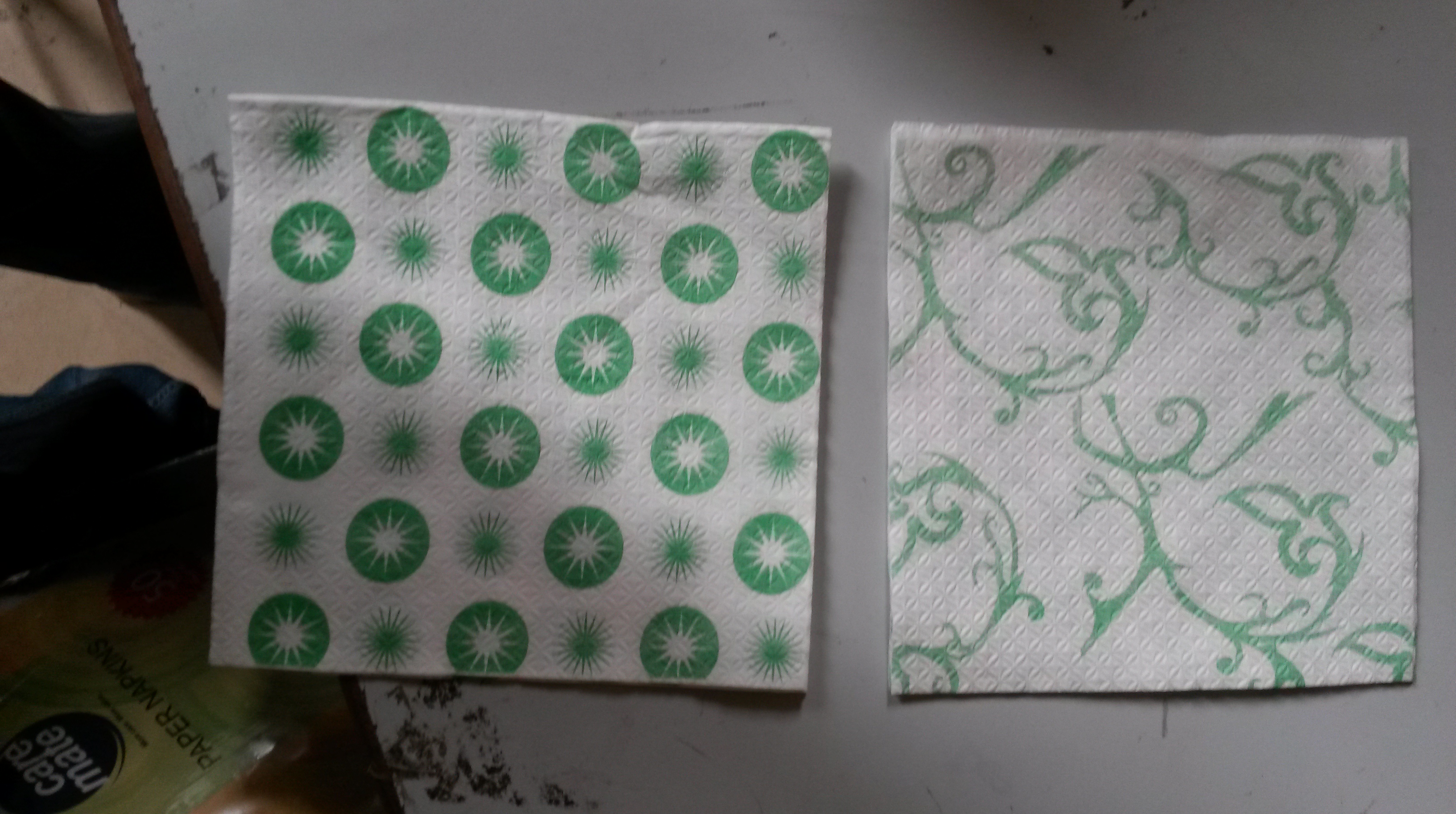
Finally, the printed, embossed and folded paper, is cut. A vertical blade is placed at the end of the machine and as the paper passes through it, it gets cut in half. As the picture shows, the napkins are split into two batches, one with each design.
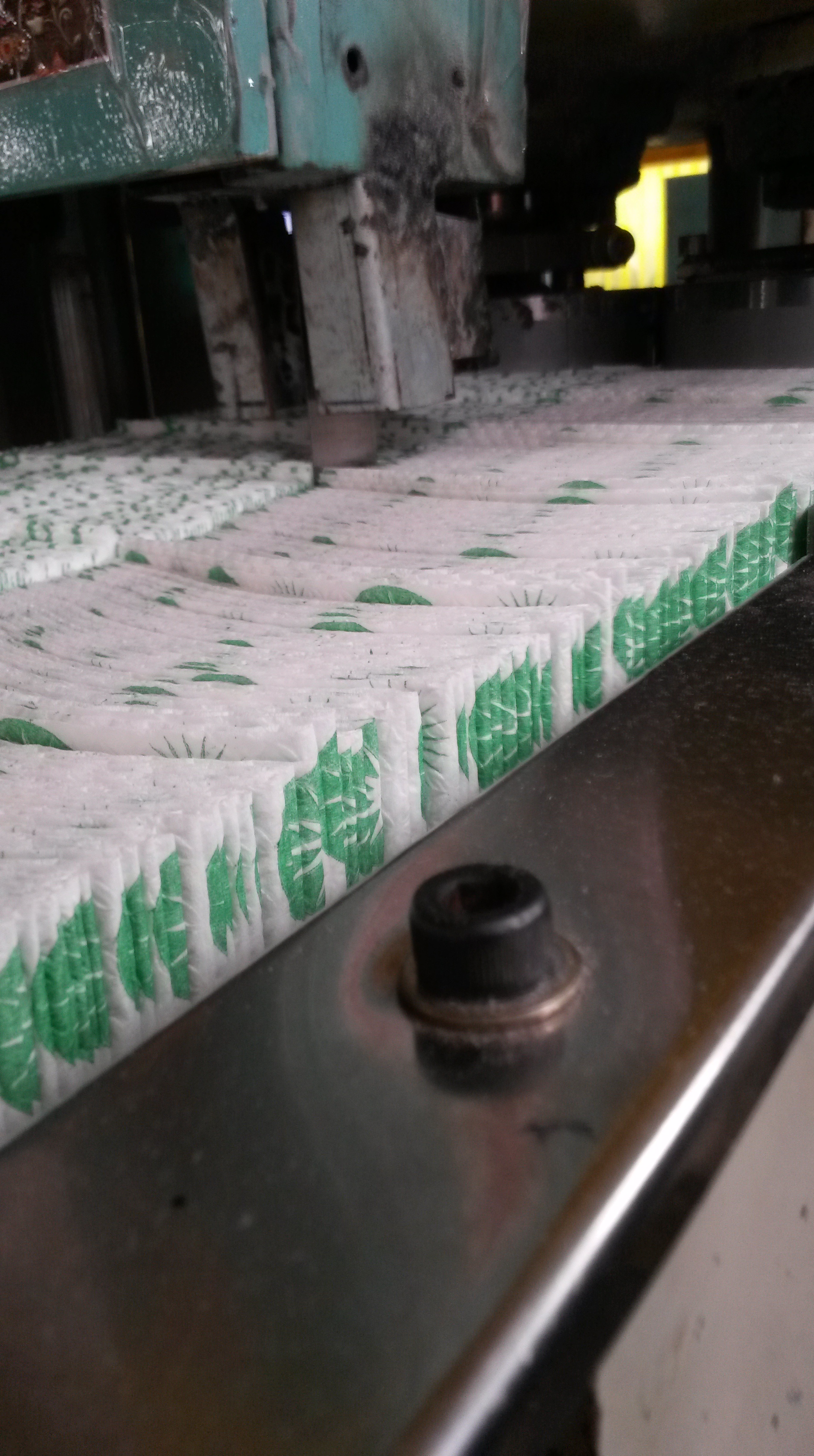
The final product of the machine is printed, embossed napkins of two different designs that are also counted.
